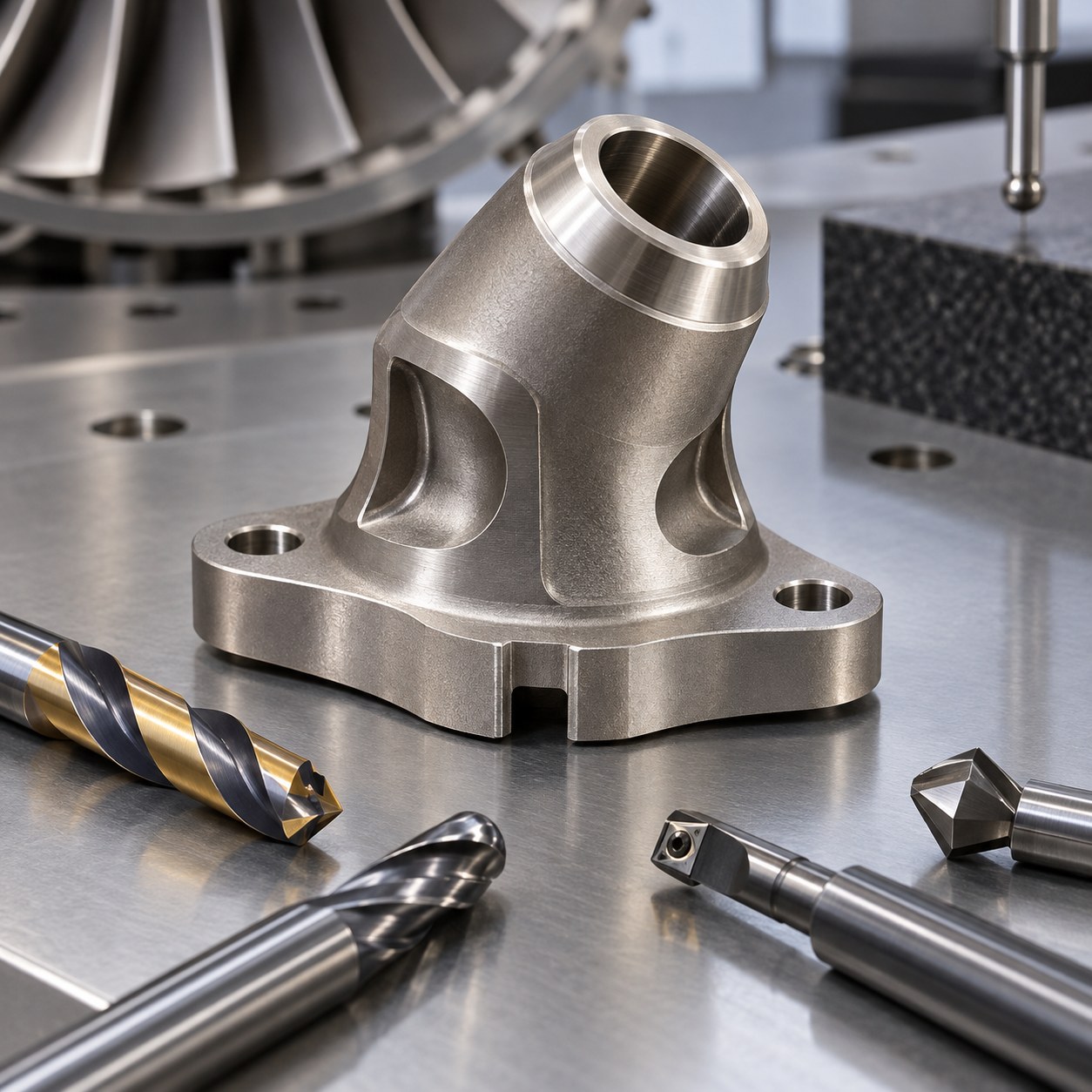
English: MAR-M247 Thermocouple Boss Tooling for Angled Bore and Seal Land
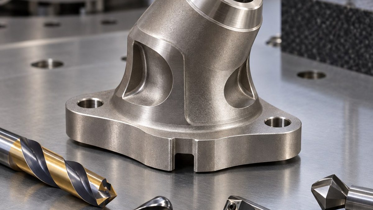
The tooling problem is to establish a compound-angle sensor axis through a cast nickel-superalloy boss, then finish a small conical seal land after the bore breaks into an irregular underside. The hypothetical flange face is datum A; two bolt holes define B-C clocking. Scallops reduce surrounding mass but are not location datums.
Establish the compound axis before deep drilling
Machine the flange and bolt datums in a three-point nest, then use a trunnion orientation calculated from A-B-C to create the normal entry pad. Drill short, verify position with a probe, continue with through coolant and leave boring stock. Rough opposing scallops in pairs, semifinish the bore, machine the wire slot, then finish the bore and seal land without changing the compound orientation.
Separate roughing, bore correction and seal finish
MAR-M247 is abrasive and heat resistant, so notch wear develops where cutters repeatedly cross cast skin. Maintain feed through bore breakthrough, use a tough PVD grade and inspect the seal tool before any offset correction. Shiny burnish, brown fines or rising torque indicates edge failure. Dwell on the small cone creates work hardening and a leak path.
Choose tools for interrupted superalloy cuts
| Drawing feature | Carbide tool and holder | Why selected / alternative rejected |
|---|---|---|
| Flange datum and bolt holes | 10 mm 5-flute variable-helix AlTiN carbide end mill, shrink holder; carbide spot drill and through-coolant drills | Rigid A-B-C frame is cut first; using a cast scallop for clocking transfers casting variation. |
| Angled entry pad and pilot | 6 mm 4-flute AlCrN carbide end mill plus 4 mm short carbide pilot drill in precision collet | A pad normal to the compound axis prevents walk; direct drilling on the slope deflects. |
| Compound-angle sensor bore | Through-coolant carbide drill, tough PVD grade, then small anti-vibration boring tool | Drill removes stock while boring corrects axis; reaming alone follows pilot drift. |
| Conical seal land | Sharp 0.2 mm-radius PVD carbide boring insert followed by narrow carbide form-finisher | Single-point cut sets position, light form pass sets angle; full-width forming chatters. |
| Cooling scallops and wire slot | 6 mm 4-flute AlTiN ball-nose mill and 3 mm 4-flute reduced-neck carbide end mill | Radius path controls interrupted entry; a long square tool notches at the cast skin. |
Inspect orientation and seal texture
CMM inspection first reconstructs the compound bore axis from flange A and bolt clocking, then measures seal diameter, angle and axial position. A borescope checks the irregular breakthrough and wire-slot intersection; surface texture is traced along the seal direction. Sensor fit, thermal cycling and engine acceptance remain separate qualified evaluations.
Practical tooling FAQ
Why bore after drilling a compound-angle hole?
The drill removes material efficiently, while boring corrects axis position and gives uniform stock to the seal land.
Why finish the seal without changing trunnion angle?
Keeping one orientation removes rotary re-index error between the bore axis and conical sealing surface.
nickel superalloy angled-hole tooling · heat-resistant alloy seal-cone tooling