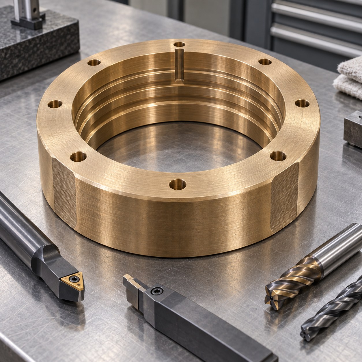
English: C63000 Pump Wear Ring Tooling for Labyrinth Steps and Lock Notch
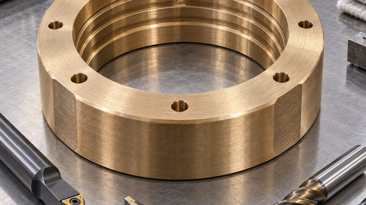
On this hypothetical fire-pump wear ring, the search problem is selecting tools that form several close internal labyrinth steps without letting a later anti-rotation notch disturb the bore axis. The drawing makes the rear mounting face and central fit bore functional; the outer casting shape is only a machining allowance. Groove height is read relative to the bore, not to the bolt heads.
Read the labyrinth as a radial stack
Face the ring on a broad soft-jaw step, rough the bore in alternating axial bands, and allow the free ring to settle before semifinishing. Bore the fit diameter and cut labyrinth floors in the same spindle grip. Clamp on a sacrificial outer band to cut the lock notch, then drill the bolt circle and mill the two flats symmetrically. Do not assume a balance flat can substitute for a measured balancing operation.
Balance stock removal around the ring
C63000 resists wear in service but still forms built-up edge under a rubbing cutter. Observe chip color and flute adhesion during groove cutting; use a fresh insert for the final floors. A narrow ring can spring under clamping, so an in-chuck indicator reading is not the released geometry. Direct coolant to evacuate chips rather than recut them in the labyrinth.
Select cutters for stepped and interrupted cuts
| Drawing feature | Carbide tool and holder | Why selected / alternative rejected |
|---|---|---|
| Rear face and fit bore roughing | 12 mm 3-flute polished ZrN carbide end mill; positive carbide drill, both in short hydraulic holders | Positive edges avoid plowing bronze; a coarse high-feed steel cutter smears the bore entry. |
| Fit bore semifinish | Polished uncoated carbide boring insert, 0.4 mm nose radius, short Capto bar | Leaves uniform stock for the labyrinth finish; two separate reamers can follow different pilots. |
| Internal labyrinth steps | 1.5 mm sharp positive carbide grooving tool with controlled 0.03 mm hone, minimum radial reach | One form width controls adjacent floors; a broad form tool engages too much bronze and chatters. |
| Anti-rotation lock notch | 4 mm 3-flute polished carbide end mill with corner radius, shrink holder | Ramp from open face and direct burr outward; a slitting saw leaves a hidden inner lip. |
| Bolt circle and balancing flats | 6 mm coolant-through carbide drill, 45° chamfer cutter and 8 mm 3-flute end mill | Drill and mill in one angular setup; hand grinding a flat cannot preserve mass distribution or edge condition. |
Measure after removing fixture pressure
After unclamping, measure fit-bore roundness and runout to the rear face. Trace each labyrinth step diameter, axial spacing and floor texture, then inspect the notch exit with magnification. Verify bolt-circle position and the mass-removal symmetry of the flats separately; any required pump balance test is beyond this drawing-based machining example.
Practical tooling FAQ
Why not cut all labyrinth steps with a wide form tool?
Its contact length raises force and chatter; a narrow positive tool keeps each floor independently adjustable.
When should wear-ring runout be accepted?
Only after release and thermal stabilization; an in-fixture measurement can mask ring springback.
pump end-cover seal groove strategy · bronze bore runout and keyway control