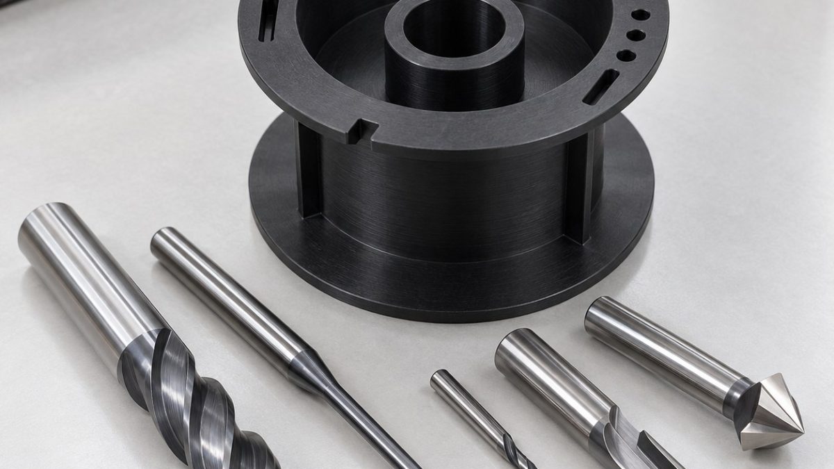
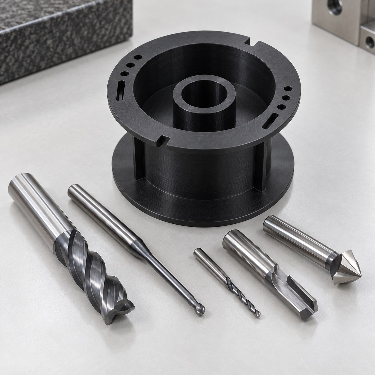
English: Noryl PPO Transformer Bobbin Tooling for Winding Pocket and Terminal Slots
The drawing question is how to open a deep annular winding pocket while keeping two thin insulating flanges square to the center bore. The hypothetical bore is datum A, the lower flange face is B and the locating notch establishes C; terminal slots are located from C so winding leads do not reduce the specified edge distance.
Interpret insulation distances from the bore
| Drawing feature | Carbide tool and holder | Why selected / alternative rejected |
|---|---|---|
| Center bore and lower datum face | 10 mm 2-flute polished uncoated carbide end mill for facing plus sharp single-edge boring tool | Low flute count avoids heat and the boring tool establishes A; a reamer can pull soft stock axially. |
| Deep annular winding pocket | 8 mm 2-flute polished radius end mill with tapered neck, balanced collet | Radius edge lowers flange-root stress and tapered neck provides reach; a long straight flute rubs the wall. |
| Thin upper and lower flanges | 6 mm 2-flute high-positive polished carbide finisher, short hydraulic holder | Alternating light face sectors limit dish; a five-flute metal cutter traps hot chips. |
| Terminal lead slots and locating notch | 1.2 mm single-flute polished carbide slot mill, precision collet | Single flute clears feather-like chips; laser trimming or hand filing can melt or round the insulating edge. |
| Terminal pin holes and edge breaks | 0.8 mm carbide drill with polished lands plus 90-degree single-flute chamfer tool | Sharp drill shears cleanly; a pecking HSS drill heats and leaves a white stress ring. |
Map pocket, flange and terminal tools
Face B and establish bore A while the stock is a thick cylinder. Rough the annular pocket in shallow helical levels while retaining a solid support ring under the upper flange. Semifinish the bore and both flange roots, allow the polymer to return to inspection temperature, then finish opposite pocket sectors alternately. Cut terminal slots and pin holes before removing the support ring; finish flange faces and the locating notch last on an expanding low-pressure arbor.
Control heat without rubbing
Noryl PPO can soften locally and produce a feathered burr when the edge loses sharpness. Use dry filtered air or an approved coolant, keep chips from packing at the pocket floor and avoid dwell near the thin flange roots. Replace the finisher when the surface turns glossy, the pin-hole rim whitens or slot width begins to taper. Do not flame-polish functional insulation edges.
Inspect geometry at conditioned temperature
Condition the bobbin before measuring bore size, flange spacing, flange squareness and the minimum wall left at every terminal slot. Use optical edge measurement for slot width and notch clocking, pin gauges for terminal holes and low-force scanning for flange dish. Dielectric strength, creepage qualification, winding fit and thermal class require separate electrical and assembly tests.
Practical tooling FAQ
Why leave a support ring under the upper flange?
It carries radial cutting load while the deep pocket is opened and is removed only after low-force features are complete.
Can terminal slots be hand-filed to size?
Not for a controlled insulating edge; filing can taper the slot, reduce edge distance and leave embedded debris.
PPSU thin latch and drainage tooling · PEEK-CF30 thin-fork tooling