English: SPKN Square Milling Inserts for Uneven Steel Plate Scale
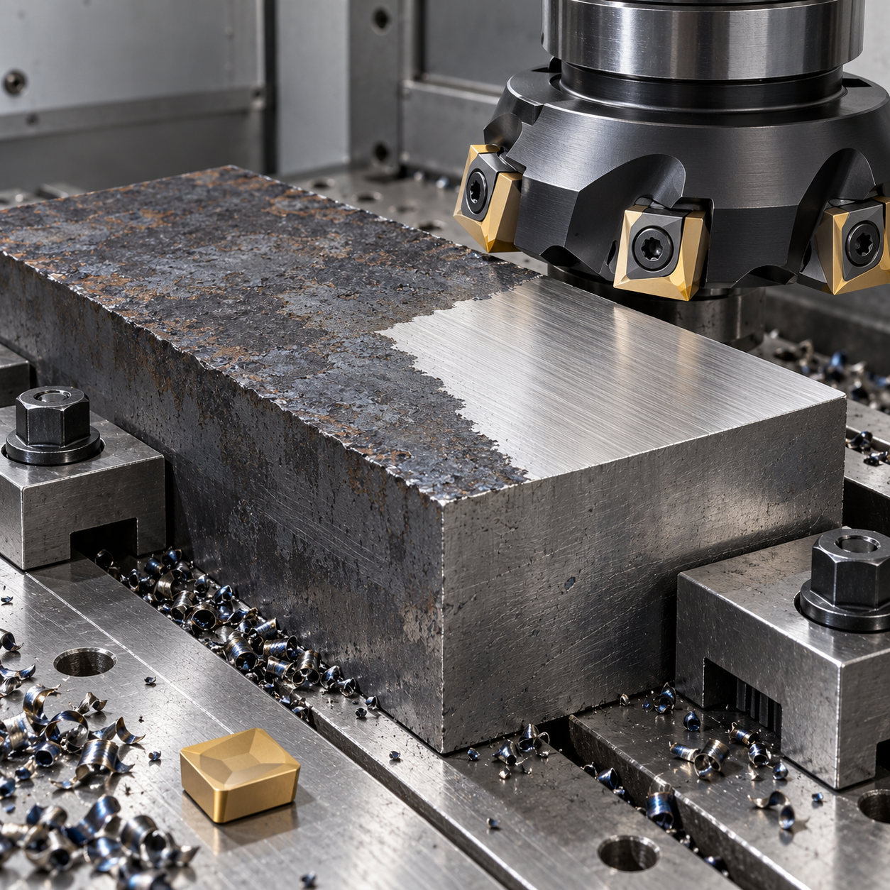
When a plate has patchy scale, choose the first face-milling pass from the measured stock envelope rather than the nominal plate thickness. This hypothetical S355 foundation shoe is 180 × 100 × 30 mm, with a 28 mm final thickness and a mounting plane perpendicular to a locating side within 0.05 mm. SPKN square carbide inserts are considered for the open face; no particular supplier’s insert is assumed to fit another supplier’s body.
Three heights that belong on the setup sheet
Record the highest scale peak, lowest sound-metal point and required finished plane from datum A. If the material envelope cannot clean up at 28 mm, stop for a drawing or stock decision. Do not silently thin the part. Support the shoe on its broad underside, use a positive end stop, and put the clamps below the cutter’s swept envelope. A hard inclusion is a material condition, not something a stronger wear offset solves.
Allocate tools by the surface they create
| Feature | Candidate | Reason |
|---|---|---|
| Scaled open face | 63 mm four-pocket face mill approved for the selected SPKN size; tough coated steel carbide, supported edge | Room for short broken chips and a secure top clamp |
| Locating side | 16 mm four-flute corner-radius carbide end mill, short hydraulic holder | Separate side datum instead of treating face-mill runout as squareness |
| Mounting clearance slots | 12 mm four-flute carbide rougher followed by a fresh wall pass | Control slot width independently of the broad face |
| Accessible edges | Two-flute 90° carbide chamfer tool | Remove scale-edge burrs without rounding the datum |
Do not replace the cleanup pass with shallow high-feed layers before checking sound-metal height. The high-feed stock and support comparison helps distinguish a suitable layer from a rubbing skim.
Compare the complete SPKN thickness, relief, edge treatment and clamp contact against the cutter drawing. A top-clamped square with no hole is not replaced by a screw-clamped square merely because its width matches. Select the manufacturer’s tough ISO-P substrate and coating for the actual scale and interrupted entry; a polished nonferrous edge and an excessively brittle wear grade are poor first trials.
Why the entry line matters more than a bigger depth
Approach from sound, supported material where possible. Keep a controlled radial engagement and sweep scale out of the next cut. For the chosen body, use its approved number of loaded pockets; fewer effective teeth are not automatically safer if they create imbalance. Establish roughing feed from actual teeth in cut, spindle torque and the supplier’s grade range. Leave an intentional finishing allowance, clean the setup, then finish with a qualified fresh edge rather than the most damaged roughing corner.
Inspect thickness at corners and centre, side-to-face squareness, slot size and Ra 3.2 µm on the mounting face. Track corner chipping, clamp seating and unexpected load peaks. Stop when a damaged edge begins rubbing scale instead of shearing it.
Questions about cleanup passes
Should the cutter skim the scale lightly? Only if that is compatible with the actual surface and tool; a rubbing skim can be less stable than a properly planned cut. Can the same edge finish? Only after inspection and qualification, not by default.
For the separate low-force finish see the ONHU thin-cover case. Before increasing feed, check the chip-load calculation guide.
Tool-system reference; the workpiece and inspection examples above are hypothetical.