English: ONHU Octagonal Finishing Inserts for Thin Steel Cover Flatness
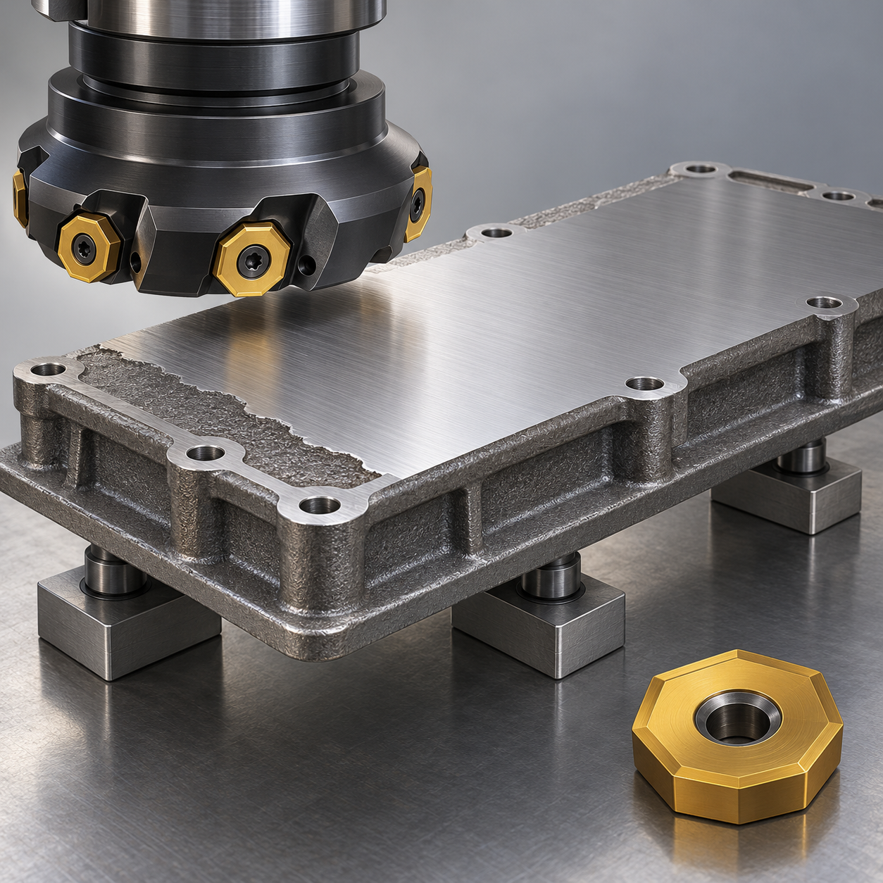
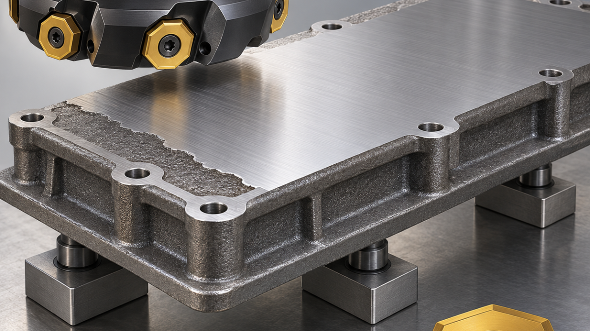
An octagonal finishing insert is useful here because the final pass must remove a controlled film of steel without bending a broad cover against its supports. It is not the tool for discovering how much casting skin remains. This hypothetical G20Mn5 cover measures 240 × 160 × 12 mm; its uninterrupted sealing face requires 0.04 mm released flatness and Ra 1.6 µm. Those are proposed drawing requirements, not reported production results.
The face has two different stock conditions
First probe the casting on three defined support pads. A low spot that survives roughing cannot be corrected by making the finishing pass arbitrarily deeper. Rough both sides as the stress condition requires, establish datum A, then map the remaining face stock. Place adjustable supports under the cutting zone without lifting the cover. Clamps bear over supports, not at an unsupported corner.
| Feature | Candidate carbide tooling | Selection boundary |
|---|---|---|
| Variable casting skin | 63 mm coarse-pitch roughing face mill, tough steel grade and moderately strengthened edge | Not the precision octagonal finishing set |
| Continuous sealing face | 80 mm finishing body with its specified ONHU-family inserts; ground perimeter, supplier-qualified steel coating | Check exact pocket, suffix, usable edge and axial-height limits |
| Four mounting bores | Short 10 mm two-flute carbide drill in a low-runout collet | Drill before the final face pass so breakthrough burrs do not mark it |
| Outer edge | 6 mm two-flute carbide chamfer mill | Keep the drawing’s 0.2 mm break outside the sealing band |
Do not purchase feed rate with extra clamp force
Use a short face arbor and inspect every loaded cutting edge, not just spindle taper runout. The proposed cutter must have enough chip space for steel chips; adding teeth is not a substitute for stiffness. Choose the exact tough carbide substrate, coating and edge preparation from the manufacturer’s steel range after confirming casting condition. A sharp unsupported edge can chip on residual skin, whereas a heavy hone can push the cover downward during a light finish.
Program an off-centre, continuous sweep with entry and exit beyond the functional face where fixture clearance permits. Keep the final allowance uniform and within the chosen finishing system’s working range; obtain speed and feed from its actual grade data. Avoid pausing over the face or returning across it with trapped chips. A broader smoothing edge may improve texture but cannot remove a tilted cutter’s geometric error.
Release the clamps before accepting the plane
Record face height under clamp and after unloading onto datum supports. Check both diagonals and the long edges, then measure roughness across and along the lay. A smooth face that springs beyond 0.04 mm still fails. Stop for edge-height drift, isolated scratches or a change in the released map; do not hide them with a larger wear offset.
The roughing proposal and this thin-cover finish should be compared under the same support condition. The high-feed guide’s compliant-part branch separates nominal productivity from released flatness.
The Invar optical-baseplate example adds a useful contrast: low thermal expansion still does not eliminate released-stress movement or the need to record support locations.
Questions before ordering an octagonal set
Are all eight-sided inserts interchangeable? No; the complete insert designation and cutter seat control fit. Can a finishing body remove the rough allowance? Only if its specified engagement range allows it; the setup above deliberately separates those jobs.
The SPKN stock-cleanup case covers the preceding roughing decision. For troubleshooting a clean-looking but uneven face, use the runout and insert-height guide.
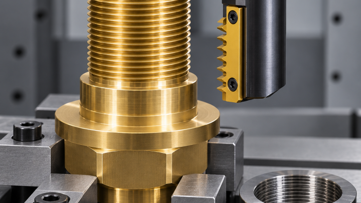
A threaded fitting seated on this cover still needs independent thread acceptance: compare the M60×2 flange-thread tooling case rather than using flatness as a substitute for gauge control.
Tool-system reference; the workpiece and inspection examples above are hypothetical.