English: Indexable Thread-Milling Inserts for M60×2 Brass Flange Threads
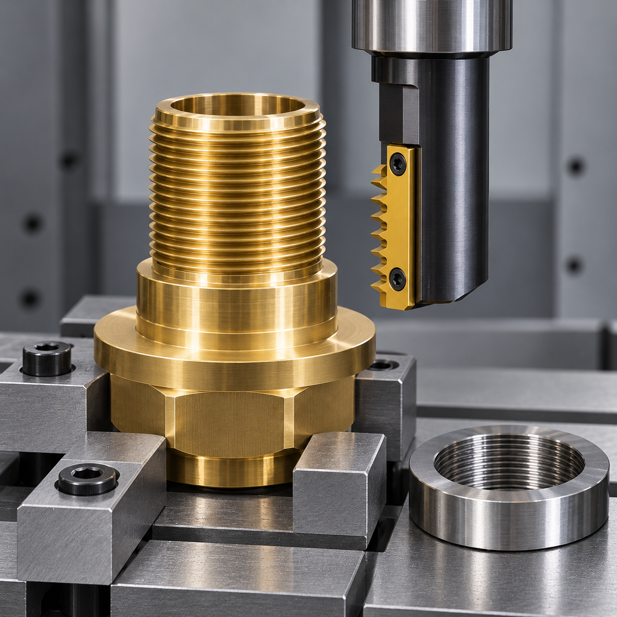
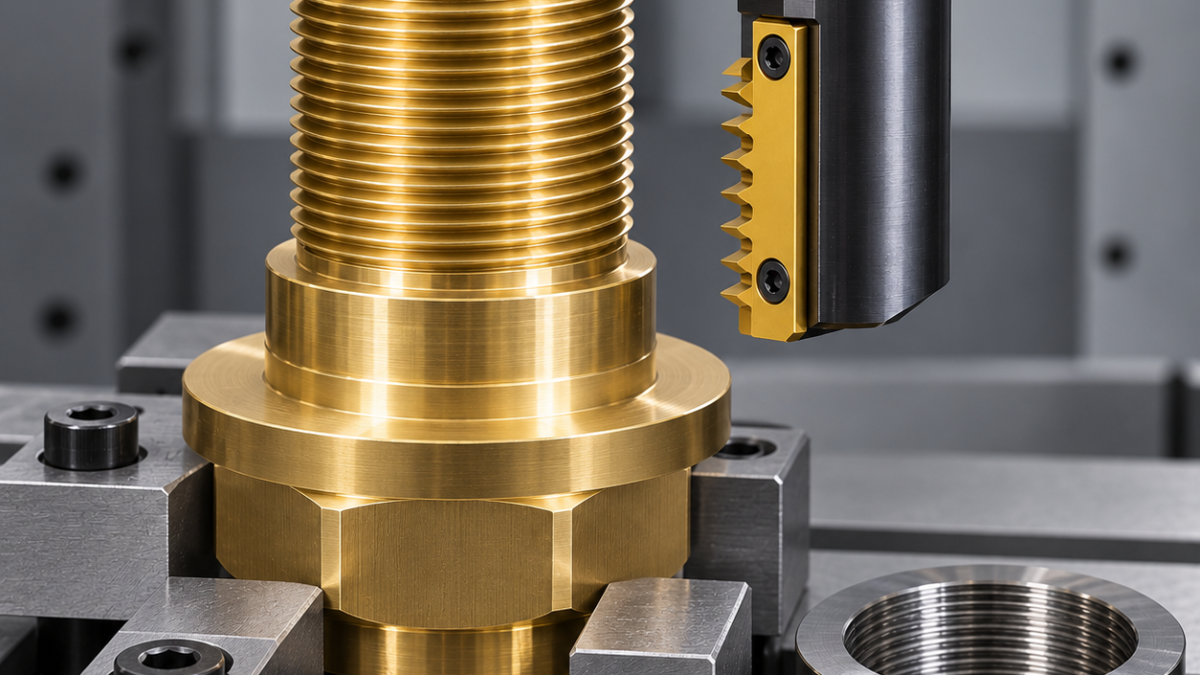
For an external M60×2 thread close to a flange, the critical insert choice is the correct external profile and pitch, followed by clearance for the entire axial tooth span. A generic 60-degree edge is not automatically a full-profile M60×2 solution. This hypothetical CuZn39Pb3 brass gland has an 18 mm usable thread length, a specified runout relief and a separate sealing shoulder. It is machined on a mill because the flange includes locating features that remain in the same setup.
Read usable thread length independently of the shoulder
Confirm the thread standard, single-start right-hand direction and required tolerance class, assumed 6g for this example. Obtain the actual size limits and gauge specification from the controlled drawing and applicable standard; do not infer them from the nominal 60 mm diameter. The relief and entrance chamfer are explicitly dimensioned. If the specified full thread reaches closer to the flange than the tool can reach, raise the conflict instead of shortening the usable thread silently.
| Drawing feature | Tool assignment | Compatibility check |
|---|---|---|
| Boss blank and shoulder | 12 mm three-flute polished-carbide end mill for external interpolation, with separate light shoulder finishing | Establish major diameter allowance and shoulder height independently |
| M60×2 external thread | Candidate 32 mm indexable thread mill with two effective circumferential teeth and an approved MT LNHU-type full-profile external 2 mm-pitch insert | Exact body, insert hand, pitch, active tooth span and clearance must match; family name alone is not an order code |
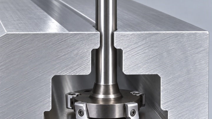
| Specified runout relief | Small carbide groove mill sized to the permitted width and root clearance | It must not cut into the sealing land |
| Lead-in and residual edge burr | Two-flute carbide chamfer cutter and accessible controlled deburring tool | Preserve the first full thread and crest shape |
One pitch per revolution is only part of the program
For a single-start 2 mm pitch, one helical revolution advances 2 mm axially. With a multi-row insert, several thread turns are produced together, so tooth-span placement and flange collision checks are essential. Model entry and exit arcs at both ends of that span, not just at the tool tip. External interpolation uses a center path outside the thread; verify whether the CAM feed is defined at the tool center or the contact contour before applying compensation.
Select a sharp, positive carbide edge appropriate for this free-machining brass, with an uncoated polished option if the exact system offers it or a supplier-qualified low-adhesion coating. Reject a steel-oriented heavily honed insert when it raises force and leaves a crest burr. Use a low-runout rigid holder with sufficient shank engagement. Clamp the gland on its back flange with located supports so helical force cannot shift its center; do not squeeze the boss into an oval.
Separate three decisions at the gauge bench
Rough the boss, finish the shoulder and major diameter, machine the specified relief, then cut the thread with a planned radial roughing and final sizing sequence. Multiple radial passes must preserve the same helical phase. Start conservatively inside the supplier’s brass-specific envelope and adjust using actual edge and chip evidence; no unverified universal speed is prescribed. Clear short brass chips from the flange recess and follow the shop’s exposure and coolant controls for lead-containing brass.
After deburring and cleaning, use the prescribed calibrated external-thread ring gauges and independently measure major diameter, usable length and shoulder location. A ring that stops at the flange is not proof that pitch diameter is oversized: check relief, the last tooth and burrs. Correct pitch diameter with the proper radial compensation only after diagnosing the cause; shifting the tool axially changes thread location, not the intended size correction. Inspect flank texture against the drawing, with a hypothetical Ra 3.2 µm target where specified, and watch crest microchipping and seat movement during tool life.
Thread-milling questions
Can an internal full-profile insert cut the same nominal external thread? Only if the manufacturer explicitly lists that insert for both uses; nominal pitch alone is insufficient. Can a 2 mm-pitch multi-row insert make 1.5 mm pitch by changing the helix? No; the physical tooth spacing remains 2 mm.
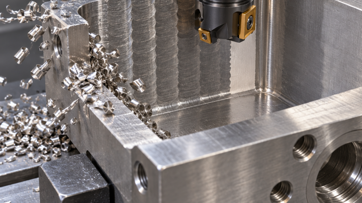
The fine-thread and sealing-seat case helps separate thread acceptance from seal geometry. A broad flat sealing face needs the different load and flatness checks illustrated by octagonal face-finishing inserts; its surface acceptance is not replaced by a thread gauge.
Tool-system reference; the workpiece and inspection examples above are hypothetical.