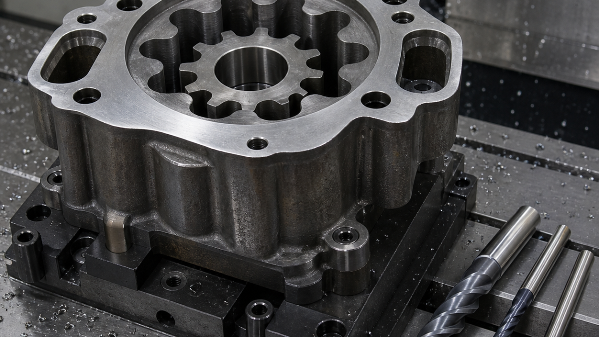
English: AISI 8620 Gerotor Housing CNC Tooling Case: Epitrochoid Bore and Carburizing Stock
An AISI 8620 gerotor housing cannot be tooled as a generic pocket. The internal epitrochoid needs a rigid rougher, a smaller bull-nose semifinisher and a precision necked finisher; crescent ports need a separate chip-clearing path; and the drawing must distinguish pre-carburizing stock from surfaces that remain soft. This hypothetical case builds the tool plan around that sequence.
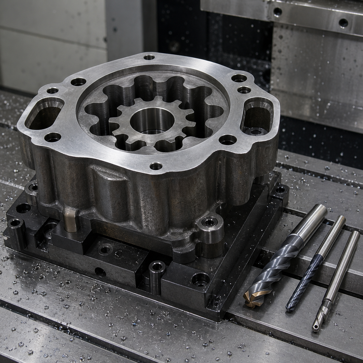
Drawing interpretation and heat-treatment intent
Mounting face A and dowel bores B-C establish the pump datum. The epitrochoid is profile-toleranced 0.025 mm to A-B-C, the rotor side clearance is developed after heat treatment, crescent ports hold 0.05 mm position, and A is flat within 0.02 mm at Ra 0.8 µm. The drawing leaves 0.18 mm per wall for post-carburizing hard finishing and masks the external mounting face from carbon. Blind oil pockets meet the profile with R0.8 minimum, so an undersized finishing tool must reach residual cusps without rubbing the full wall.
Feature-to-tool selection table
| Drawing feature | Selected tool and holder | Rationale / alternative rejected |
|---|---|---|
| Datum face A | Ø50, six-insert positive face mill, PVD-coated P25 carbide, 0.8 mm wiper, rigid arbor | Stable in normalized 8620 with interrupted skin. PCD is rejected because ferrous cutting causes rapid chemical wear. |
| Epitrochoid bulk roughing | Ø16, 5-flute variable-pitch AlTiN carbide, 0.1 mm edge hone, 32 mm reach, hydraulic holder | High metal removal with a tough edge. A four-flute long cutter lacks radial stiffness at the deepest lobes. |
| Profile semifinish | Ø8, 5-flute TiAlN bull nose R0.5, relieved neck, 38 mm reach, shrink holder | Equalizes stock through concave lobes while protecting the corner. A ball nose creates excessive scallop and axial force. |
| Pre-carburizing profile finish | Ø6, 6-flute high-precision AlCrN carbide, R0.2, necked shank, shrink holder with runout below 0.005 mm | Reaches residual geometry and leaves uniform 0.18 mm. A Ø4 tool would be more flexible without adding access. |
| Crescent ports | Ø5, 4-flute coated carbide, chip-splitter geometry, through-coolant hydraulic chuck | Trochoidal paths control slot load. Full-width plunging with a standard end mill traps chips. |
| Dowel bores B-C | Carbide pilot drill, Ø9.5 through-coolant drill and fine-boring head to pre-heat size | Boring secures position and controlled hard-finish stock; a reamer follows drill drift. |
| Port edge chamfers | Ø10, 4-flute AlTiN carbide chamfer mill, 90°, short projection | Controlled break before carburizing; hand blending would vary the carbon-case edge. |
Roughing, fixture and carburizing handoff
A is faced first, and B-C pilots are established from the same setup. A rigid tombstone nest then locates on A with two expanding pins and supports the housing beneath the lobe ring. The Ø16 tool uses high-efficiency milling at less than 10% radial engagement, leaving 0.60 mm. The Ø8 bull nose follows a constant-cusp morph between the mathematical curves, leaving 0.28 mm. The Ø6 finisher makes two axial bands per lobe and leaves the specified 0.18 mm hard-finishing stock rather than chasing final rotor clearance in the soft condition.
Crescent ports are machined after the cavity so their breakthrough burr is accessible. The Ø5 cutter starts in a drilled relief, uses trochoidal arcs and alternates the two ports to distribute heat. Chips are evacuated with through-coolant and air only when permitted by the enclosure. Tool-life alarms track spindle-load slope, corner chipping and lobe-to-lobe stock variation. After carburizing, datum A is lightly ground, B-C are hard-finished, and the epitrochoid is completed by the qualified hard-finishing or grinding process from the restored datum frame.
Inspection and search-focused FAQ
Before heat treatment, a CMM scans each lobe at three axial levels and reports actual stock against the nominal finished profile, not merely the soft-stage contour. Port position, minimum web, B-C relation and A flatness are recorded for heat-treatment compensation. After carburizing, hardness and case depth follow the drawing; the restored A-B-C frame is used for final profile, rotor clearance, port blending and surface-finish verification.
Which end mill should finish an epitrochoid bore before carburizing?
Use the largest necked precision tool that reaches every concavity; here Ø6 with six flutes and controlled runout leaves uniform hard-finishing stock.
Why not machine the gerotor profile to final size before heat treatment?
Carburizing and quenching can distort the thin lobe ring. Defined stock allows the final profile to be restored from the hardened datum system.
How are crescent-port burrs prevented from damaging the cavity?
Machine ports after cavity roughing, use a chip-splitting trochoidal path, flush breakthrough chips outward and apply a programmed chamfer before heat treatment.
Related reading: carburizing allowance and datum restoration and hardening-stock inspection planning.
中文: AISI 8620摆线泵壳配刀:内摆线轮廓、月牙口与渗碳余量
AISI 8620摆线泵壳不能按普通型腔配刀。内摆线轮廓需要刚性开粗刀、牛鼻半精刀和缩颈精刀逐级接力;月牙形进出油口要用独立排屑刀路;图纸还必须区分渗碳后要硬精加工的表面和防渗碳软面。本假设案例把配刀与热处理交接放在同一逻辑中。
图纸与热处理余量
A安装面与B、C定位孔建立泵体基准。内摆线对A-B-C轮廓度0.025 mm,月牙口位置度0.05 mm,A面平面度0.02 mm、Ra 0.8 µm。图纸规定轮廓每侧留0.18 mm渗碳后硬精余量,外部安装面防渗碳;盲油腔与轮廓交界最小R0.8,因此精刀要进入残料区但不能整壁摩擦。
特征—刀具选择表
| 图纸特征 | 刀具与刀柄 | 选择及排除理由 |
|---|---|---|
| A面 | Ø50六刀片正前角面铣刀,PVD P25硬质合金,R0.8修光刃 | 适合正火8620断续皮;PCD加工铁基材料会快速化学磨损。 |
| 内摆线开粗 | Ø16五刃变齿AlTiN刀,0.1 mm刃口强化,悬伸32 mm,液压刀柄 | 去除率与韧性兼顾;四刃长刀在深波谷径向刚性不足。 |
| 轮廓半精 | Ø8五刃TiAlN牛鼻刀R0.5,缩颈38 mm,热缩刀柄 | 均化凹部余量并保护刀尖;球刀扇形纹和轴向力过大。 |
| 渗碳前精轮廓 | Ø6六刃高精度AlCrN刀R0.2,缩颈,跳动小于0.005 mm | 覆盖全部凹部并均匀留0.18 mm;Ø4更软却无额外可达性。 |
| 月牙口 | Ø5四刃涂层硬质合金,分屑槽,内冷液压夹头 | 摆线刀路稳定槽负载;普通刀满槽下压会困屑。 |
| B、C孔 | 硬质合金定心钻+Ø9.5内冷钻+精镗头 | 控制孔位及硬精余量;铰刀跟随钻孔漂移。 |
| 月牙口倒角 | Ø10四刃AlTiN 90°倒角刀,短悬伸 | 渗碳前统一边缘,手工修磨会改变硬化层边界。 |
装夹、刀路和渗碳交接
第一序加工A面并建立B、C预孔;第二序在刚性立式夹具上以A面和两个胀销定位,内摆线环下方增加支承。Ø16以小于10%径向吃刀量动态开粗,留0.60 mm;Ø8按数学曲线做等残高半精,留0.28 mm;Ø6在每个波瓣分两层轴向带精加工,最终严格保留0.18 mm,不在软态追求转子成品间隙。
型腔完成后再加工月牙口,使出口毛刺可见可达。Ø5从预钻让位孔进入,以摆线圆弧交替加工两个口并持续内冷排屑。主轴负载斜率、刀角崩损和各波瓣余量差作为换刀信号。渗碳后轻磨A面,恢复B、C,再从恢复后的基准系进行内摆线硬精或磨削。
检验与常见问题
热处理前三坐标在三个轴向层面扫描每个波瓣,直接报告相对成品数学轮廓的实际余量,同时记录月牙口位置、最小筋厚、B-C关系和A面平面度,为热处理补偿提供依据。渗碳后按图检查硬度和层深,再以A-B-C复核最终轮廓、转子间隙、口部过渡和粗糙度。
渗碳前内摆线用多大刀精加工?
选能到达所有凹部的最大缩颈精刀;本例Ø6六刃刀在小跳动条件下均匀留硬精余量。
为什么软态不直接做到成品尺寸?
渗碳淬火可能使薄波瓣环变形,明确余量才能从硬化后的基准恢复轮廓。
月牙口毛刺怎样控制?
型腔后加工、分屑摆线刀路向外冲屑,并在热处理前用程序倒角统一边缘。
Français: Carter de gérotor 8620 : profil épitrochoïde et réserve de cémentation
Le carter de gérotor en AISI 8620 n’est pas une poche ordinaire. Une fraise rigide enlève le volume, une torique égalise les lobes, une fraise dégagée laisse la réserve de cémentation, tandis que les lumières en croissant reçoivent un parcours séparé à bonne évacuation.
Plan et état thermique
A et les pions B-C définissent la pompe. Le profil épitrochoïde vaut 0,025 mm, les lumières 0,05 mm et A 0,02 mm à Ra 0,8 µm. Chaque paroi conserve 0,18 mm pour la finition dure après cémentation; A est masquée.
Tableau fonction–outil
| Fonction | Outil | Décision |
|---|---|---|
| Face A | Fraise Ø50, 6 plaquettes P25 PVD positives, racleur R0,8 | Stable dans 8620; PCD s’use chimiquement sur le fer. |
| Ébauche | Ø16, 5 dents variables AlTiN, arête 0,1 mm, portée 32 mm | Rigidité dans les lobes profonds. |
| Semi-finition | Torique Ø8, 5 dents TiAlN, R0,5, col 38 mm | Uniformise la matière; une boule pousse axialement. |
| Préfinition | Ø6, 6 dents AlCrN, R0,2, col dégagé, faux-rond <0,005 mm | Atteint toutes les concavités et laisse 0,18 mm. |
| Lumières croissant | Ø5, 4 dents revêtues à brise-copeaux, arrosage central | Trochoïde sans coupe en pleine largeur. |
| Pions | Foret carbure Ø9,5 puis alésage fin | Position et réserve maîtrisées. |
| Chanfreins | Carbure AlTiN Ø10, 4 dents, 90° | Bord constant avant cémentation. |
Parcours et transfert thermique
Le montage soutient l’anneau sous les lobes. Ø16 ébauche sous 10% d’engagement et laisse 0,60 mm; Ø8 suit une morphologie à crête constante jusqu’à 0,28 mm; Ø6 travaille deux bandes axiales et conserve 0,18 mm. Les croissants sont usinés ensuite depuis un trou de décharge, en alternance.
Charge, ébréchure et différence de matière entre lobes commandent le remplacement. Après cémentation, A est rectifiée légèrement, B-C sont restaurés et le profil est fini dur depuis ces références.
Contrôle et FAQ
Avant traitement, la MMT scanne trois niveaux et calcule la réserve par rapport au profil final. Après traitement, dureté, profondeur de couche, profil et jeu rotor sont contrôlés dans A-B-C.
Quelle fraise de préfinition?
La plus grande fraise dégagée atteignant les creux; ici Ø6 à six dents.
Pourquoi garder 0,18 mm?
Pour corriger la déformation de cémentation.
Comment éviter les bavures des croissants?
Usiner après la cavité, évacuer vers l’extérieur et chanfreiner par programme.
Voir la réserve de cémentation et le contrôle avant trempe.
Русский: Корпус геротора 8620: профиль и припуск цементации
Корпус героторного насоса AISI 8620 требует цепочки инструментов: жёсткая фреза удаляет объём, тороидальная выравнивает лопасти, шейковая оставляет припуск цементации, а серповидные окна получают отдельную траекторию с отводом стружки.
Чертёж и термообработка
A и штифты B-C задают базу. Профиль эпитрохоиды 0,025 мм, окна 0,05 мм, плоскостность A 0,02 мм при Ra 0,8 мкм. На стенках оставляют 0,18 мм для твёрдой отделки после цементации; A защищают.
Таблица элемент–инструмент
| Элемент | Инструмент | Почему |
|---|---|---|
| A | Ø50, шесть позитивных PVD P25 пластин, зачистная R0,8 | PCD химически изнашивается по железу. |
| Черновая | Ø16, 5 переменных зубьев AlTiN, кромка 0,1 мм, вылет 32 мм | Жёсткость в глубоких лопастях. |
| Полуфиниш | Тороидальная Ø8, 5 зубьев TiAlN, R0,5, шейка 38 мм | Равномерный припуск без осевой силы шара. |
| Предфиниш | Ø6, 6 зубьев AlCrN, R0,2, биение <0,005 мм | Достигает впадин и оставляет 0,18 мм. |
| Серповидные окна | Ø5, 4 зуба с делителем стружки и внутренней СОЖ | Трохоидальная траектория без полного паза. |
| B-C | Карбидное сверло Ø9,5 и тонкая расточка | Положение и припуск под контролем. |
| Фаски | AlTiN Ø10, 4 зуба, 90° | Постоянная кромка до цементации. |
Траектория и передача
Опора стоит под кольцом лопастей. Ø16 при зацеплении ниже 10% оставляет 0,60 мм; Ø8 идёт с постоянным гребешком до 0,28 мм; Ø6 делает две осевые полосы и сохраняет 0,18 мм. Окна обрабатывают после полости от разгрузочного отверстия.
Рост нагрузки, скол угла и разный припуск между лопастями задают смену. После цементации A слегка шлифуют, B-C восстанавливают и профиль заканчивают от твёрдых баз.
Контроль и вопросы
До термообработки КИМ сканирует три уровня и считает припуск к финальному профилю. После неё проверяют твёрдость, глубину слоя, профиль и зазор ротора.
Какая фреза для предфиниша?
Максимальная шейковая, достигающая всех впадин; здесь Ø6, шесть зубьев.
Зачем оставлять 0,18 мм?
Чтобы исправить деформацию цементации.
Как убрать заусенец окон?
Обрабатывать после полости, промывать наружу и программно фасить.


