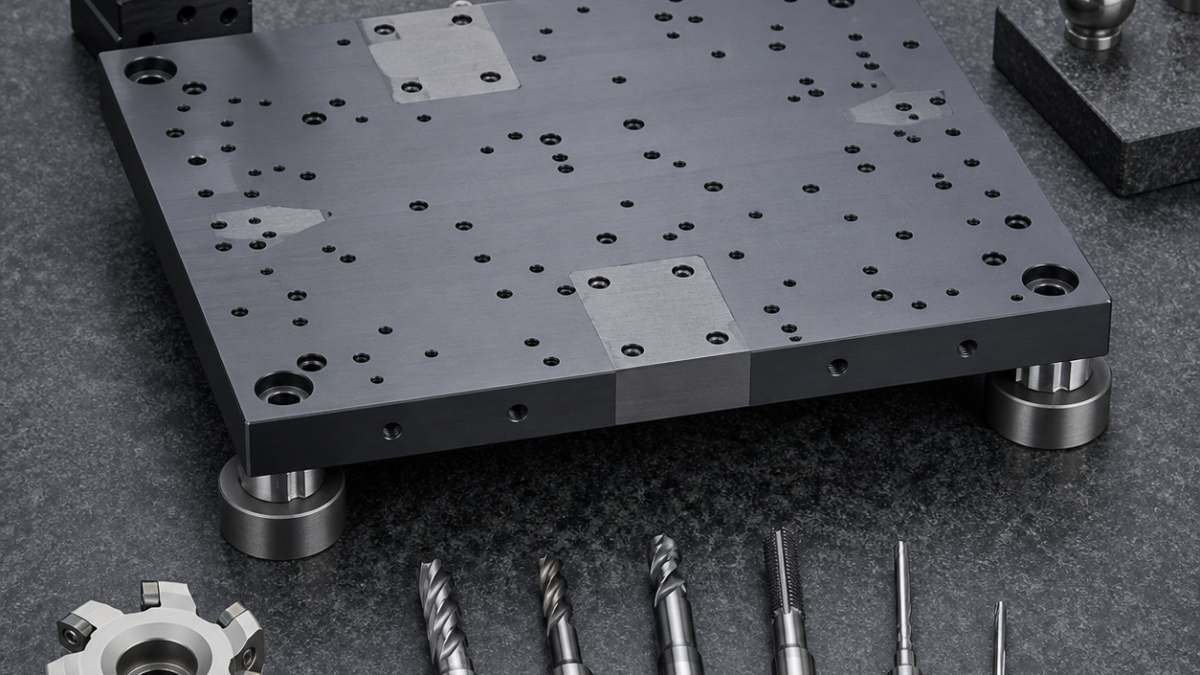
This is a realistic hypothetical process-planning example, not a claim about a specific customer drawing or production result.
Related: See our copper heat-sink flatness case and counterbore and threaded-hole tooling case.
English: reading the optical-baseplate drawing
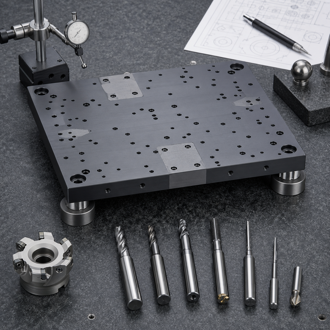
This hypothetical Invar 36 baseplate combines a precision reference face, raised datum pads, counterbores, dowel holes and a dense threaded pattern. Low thermal expansion helps the assembly, but the alloy work-hardens and conducts heat poorly, so flatness depends on both cutting and thermal discipline.
Feature and datum plan
Separate functional datum pads from clearance features. Establish the lower support face first, map hole groups from one coordinate origin, and reserve the top reference face for a light final pass after drilling has released local stress.
Tool selection
Use a positive-rake face mill with sharp inserts, coated carbide stub drills, a carbide reamer for locating holes, and thread mills for small or costly threads. Thread milling reduces torque and permits diameter correction. A 90-degree chamfer tool should touch only after hole inspection.
Fixture and process strategy
Support the plate at three defined points with low, repeatable clamp force. Rough both faces in balanced stages, drill from a verified datum state, then unclamp and allow temperature equalization before the final face cut. Where possible, group tools by heat input rather than simply minimizing changes.
Flatness and tool-life risks
Over-clamping can create a false flat result; heat from dense drilling can produce coordinate drift. Use through-tool coolant where permitted, peck only as needed, monitor spindle load and replace drills before margin wear grows. Verify flatness at controlled temperature after the plate rests free.
FAQ
Why use thread milling instead of taps?
It lowers torque, improves chip control and allows one cutter to cover related diameters.
Should all holes be made before finish facing?
Usually yes for stress balance, but protect critical pads and confirm the drawing’s positional reference scheme.
中文:解读Invar 36光学基板图纸
本假设基板包含精密基准面、凸起定位垫、沉孔、销孔和密集螺纹孔。Invar 36低热膨胀有利于装配,但材料易加工硬化且导热差,因此平面度控制必须同时考虑切削热、装夹力和工序释放。
特征与基准规划
将功能定位垫与普通避让孔分开管理。先建立下支承面,所有孔组使用统一坐标原点;密集钻孔释放局部应力后,再对上基准面进行轻量精加工。
刀具选择
面铣采用锋利正前角刀片,孔加工使用涂层硬质合金短钻,定位孔用硬质合金铰刀,重要小螺纹优先螺纹铣削。螺纹铣刀扭矩低、便于修正中径,最后用90度倒角刀轻触孔口。
装夹与工艺策略
采用三个确定支承点并限制夹紧力。两面分阶段对称去料,在确认基准后完成孔系;卸夹并达到温度平衡后再精铣顶面。刀具排序还应考虑热输入,不能只追求最少换刀。
平面度与刀具寿命风险
过度夹紧会造成虚假平面度,密集钻孔的热量会引起坐标漂移。允许时使用内冷,按需要排屑而不过度啄钻,监控主轴负载并在钻头刃带磨损扩大前更换。最终应在控温且自由状态下检测。
常见问题
为何采用螺纹铣削而不是丝锥?
它能降低扭矩、改善排屑,并允许通过程序补偿中径。
是否应在精铣前完成全部孔?
通常有利于应力平衡,但必须依据图纸的形位基准关系确定。
Français : lire le plan du plateau optique
Ce plateau hypothétique en Invar 36 réunit face de référence, plots, lamages, trous de pion et réseau taraudé dense. Sa faible dilatation est utile, mais l’écrouissage et la faible conductivité imposent une gestion stricte de la chaleur et du bridage.
Plan des fonctions et références
Distinguer les plots fonctionnels des trous de dégagement. Créer d’abord la face d’appui, programmer tous les groupes depuis une origine commune, puis réserver une passe légère sur la face supérieure après le perçage.
Choix des outils
Employer une fraise à surfacer positive, des forets carbure courts revêtus, un alésoir pour les pions et des fraises à fileter. Le fraisage du filet réduit le couple et permet une correction du diamètre; le chanfreinage intervient après contrôle.
Bridage et gamme
Porter la plaque sur trois points et limiter l’effort de serrage. Ébaucher les deux faces par étapes équilibrées, percer depuis les références vérifiées, puis laisser la température s’équilibrer avant la finition.
Risques de planéité et d’usure
Un serrage excessif masque la déformation; la chaleur du perçage dense décale les positions. Surveiller la charge, évacuer les copeaux et contrôler la planéité à température stabilisée, pièce libre.
FAQ
Pourquoi fraiser les filets ?
Le couple est moindre et le diamètre reste compensable.
Percer avant la finition ?
Souvent oui pour libérer les contraintes, sous réserve du système de références du plan.
Русский: анализ чертежа оптической плиты
Условная плита из Invar 36 имеет точную базовую поверхность, опорные площадки, цековки, отверстия под штифты и плотную сетку резьб. Низкое расширение полезно, но наклеп и слабая теплопроводность требуют контроля тепла и усилия зажима.
План баз и элементов
Функциональные площадки отделяют от вспомогательных отверстий. Сначала создают нижнюю опору, все группы программируют от единого начала координат, а верхнюю плоскость чистят после сверления.
Выбор инструмента
Нужны торцевая фреза с положительной геометрией, короткие твердосплавные сверла, развертка для штифтов и резьбовая фреза. Последняя снижает момент и позволяет корректировать диаметр.
Оснастка и маршрут
Плиту опирают на три точки и ограничивают зажим. Обе стороны черновят симметрично, сверлят после проверки баз, затем дают детали выровнять температуру и выполняют чистовой проход.
Риски плоскостности и стойкости
Сильный зажим скрывает деформацию, а тепло плотного сверления смещает координаты. Контролируют нагрузку, отвод стружки и проверяют плоскостность свободной детали при стабильной температуре.
FAQ
Зачем фрезеровать резьбу?
Это снижает момент и дает коррекцию размера.
Сверлить до чистового прохода?
Обычно да, если это соответствует системе баз чертежа.


