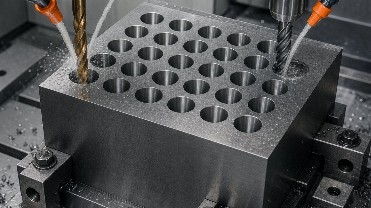
English: Tungsten Heavy-Alloy Collimator CNC Case: Tapered Bore Array and Axis Control
A tungsten heavy-alloy collimator with twenty-four tapered passages is controlled by validating the first bore completely, then managing thermal drift and tool wear across the array. This hypothetical case explains why merely gauging entry diameters misses the critical search intent: keeping every tapered bore axis within the positional cone while machining a dense, abrasive material.
The drawing defines an axis, not just two diameters
Datum A is the mounting face, B and C are orthogonal side datums. Each 38 mm-deep passage tapers from Ø10.0 to Ø7.6 mm and has a true-position cylinder of Ø0.06 mm relative to A-B-C; included-angle tolerance is ±0.04 degrees and exit breakout is limited to 0.08 mm. Array pitch is basic. Density makes the block heavy, so fixture lifting and support are part of the process plan.
Prove one hole before committing the array
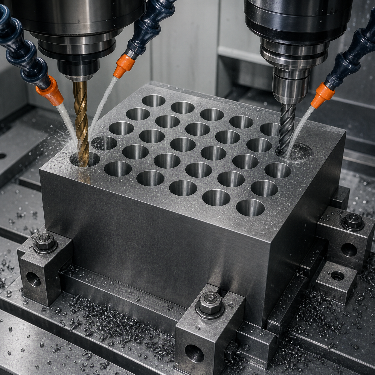
A rough carbide face mill establishes A-B-C. The block rests on a full-area hardened support with positive side stops and hydraulic clamps close to the load path. A coated through-coolant carbide drill creates a pilot, followed by helical interpolation with a short coated carbide end mill. A tapered carbide reamer is tested only after the interpolated geometry is measured; it is not trusted to correct an off-axis pilot.
The first passage is cut at production parameters, cleaned and inspected for axis, taper, finish and exit edge. Only then is the array released. Holes are machined in a balanced center-out sequence to distribute heat. Each pilot uses full retract chip evacuation and verified coolant flow. Helical semifinishing leaves 0.05 mm radial stock; a fresh finishing path uses cutter compensation derived from the first-bore data.
Toolpaths address mass, abrasion and chip packing
Tungsten heavy alloy generates high cutting force and dense chips that settle quickly. The process avoids long dwells and rubbing at the small exit. Entry arcs are tangential; helix pitch decreases near breakthrough, and a sacrificial backing plate supports the exit. Coolant nozzles are checked by pressure, not visual splash. Tools are grouped in small monitored lots because flank wear shifts both taper and axis.
Inspection uses depth, not a single circle
A probe verifies A-B-C and fixture shift before each row. Bore axes are reconstructed from noncontact or calibrated stylus circles at four depths; entrance and exit diameters alone are insufficient. A CMM reports position, angle and pitch, while an air taper gauge checks form. Microscopy measures breakout and carbide transfer. Surface finish is sampled with a suitable small-bore method, and a final cleanliness check confirms no dense chip remains trapped.
FAQ
Can a tapered reamer correct a misaligned tungsten-alloy hole?
Not reliably. It tends to follow the pilot; helical interpolation establishes the axis before any sizing tool is used.
How is tapered-bore axis position measured?
Collect circles at several depths in the A-B-C frame, fit the bore axis and taper, then evaluate true position and angle.
What limits carbide tool life in tungsten heavy alloy?
Abrasive flank wear, high force, heat and chip packing. This case monitors bore trend, load and tool microscopy instead of assigning an unsupported fixed count.
Related reading: compound-angle hole metrology and axis correction versus following tools.
中文: 钨重合金准直器加工:锥孔阵列与孔轴控制
二十四孔钨重合金准直器的稳妥路线,是先完整验证首孔,再管理整列加工中的温漂和刀具磨损。只量入口直径无法回答真正问题:每个锥孔轴线都必须落在位置公差柱内。本假设案例围绕这一长尾搜索意图展开。
图纸控制的是空间轴线
A为安装面,B、C为互相垂直的侧基准。每孔深38 mm,由Ø10.0收至Ø7.6 mm,相对A-B-C的位置度为Ø0.06 mm,锥角公差±0.04°,出口崩口不大于0.08 mm。阵列节距采用基本尺寸。材料密度高,因此全底支撑和安全吊装也属于工艺设计。
首孔合格后才放行阵列
硬质合金面铣刀建立A-B-C,工件落在整面硬化支撑上,侧向止挡和液压夹紧靠近受力路径。内冷涂层硬质合金钻打预孔,短硬质合金立铣刀螺旋插补建立轴线;锥度铰刀只有在插补孔测量合格后才进行试验,不能指望它纠正偏斜预孔。
首孔按正式参数完成并检查轴线、锥度、粗糙度和出口边缘。阵列随后按中心向外的平衡顺序加工。预孔周期包含完全退刀排屑并确认冷却压力;螺旋半精每侧留0.05 mm,精补偿由首孔数据生成。
高密度切屑和磨粒磨损
钨重合金切削力高,沉重切屑易在深孔底部堆积。刀路避免小端长时间停留和摩擦,切入采用相切圆弧,接近出口时减小螺距,背面用牺牲支撑板。冷却液以压力数据确认,不以“看见有水”判断。硬质合金刀具按小批量监控,侧面磨损会同时改变锥度与轴线。
分深度重建孔轴
每加工一排前,测头复核A-B-C与夹具漂移。三坐标或非接触测量在四个深度采集圆截面,拟合轴线和锥角,再评价位置度、角度和节距;气动锥度量仪检查形状,显微镜量出口崩口。小孔粗糙度用适配方法抽检,最终清洁确认无重切屑滞留。
常见问题
锥度铰刀能纠正偏孔吗?
通常不能,它会随预孔;本案例先用螺旋插补建立轴线。
锥孔轴线怎样测?
在A-B-C坐标系内分多个深度采圆,拟合孔轴和锥度,再评价位置度和角度。
钨重合金中什么决定硬质合金刀寿命?
磨粒磨损、高切削力、热量和堵屑,应看孔趋势、负载和刃口显微状态。
Français: Collimateur en alliage de tungstène : réseau d’alésages coniques
Le contrôle d’un collimateur à vingt-quatre passages commence par la validation complète du premier trou, puis par la maîtrise de la dérive et de l’usure. Mesurer seulement les diamètres d’entrée ne garantit pas l’axe.
Le plan impose un axe spatial
A est la face, B et C les côtés. Chaque passage de 38 mm va de Ø10,0 à Ø7,6 mm, avec position Ø0,06 mm, angle ±0,04° et éclat de sortie 0,08 mm. Le support intégral tient compte de la masse élevée.
Valider le premier passage
Une fraise carbure crée A-B-C. Un foret carbure arrosé pilote, puis une fraise courte interpole l’hélice. L’alésoir conique n’est essayé qu’après mesure: il ne corrige pas un pilote incliné. Le premier passage est contrôlé entièrement avant un ordre centre-vers-extérieur; la semi-finition laisse 0,05 mm.
Copeaux lourds et trajectoire
Les retraits complets et la pression d’arrosage évitent le tassement. L’entrée est tangentielle, le pas diminue près de la sortie et une plaque martyr soutient la percée. L’usure de dépouille est suivie par petits lots, car elle déplace cône et axe.
Mesurer en profondeur
Le palpeur revalide A-B-C avant chaque rangée. Des cercles à quatre profondeurs reconstruisent axe et cône; la MMT rapporte position, angle et pas. Un calibre pneumatique, la microscopie de sortie et le contrôle de propreté complètent l’inspection.
FAQ
Un alésoir corrige-t-il l’axe ?
Non de façon fiable; l’interpolation établit d’abord l’axe.
Comment mesurer l’axe conique ?
Ajuster des cercles à plusieurs profondeurs dans A-B-C.
Quel risque pour le carbure ?
Usure abrasive, effort, chaleur et tassement des copeaux.
Voir les trous inclinés et les outils correcteurs.
Русский: Вольфрамовый коллиматор: массив конических отверстий
Для массива из двадцати четырёх каналов сначала полностью подтверждают первый канал, затем управляют дрейфом и износом. Одних входных диаметров недостаточно для контроля оси.
Чертёж задаёт ось
A — монтажная плоскость, B и C — боковые базы. Канал глубиной 38 мм идёт от Ø10,0 до Ø7,6 мм; позиция Ø0,06 мм, угол ±0,04°, скол 0,08 мм. Большая масса требует сплошной опоры.
Первый канал как разрешение процесса
Твердосплавная фреза создаёт A-B-C. Сверло с внутренней подачей делает пилот, короткая фреза интерполирует ось. Коническую развёртку проверяют только после измерения: она не исправляет наклон. Первый канал контролируют полностью, затем массив режут от центра наружу, оставляя 0,05 мм.
Стружка и износ
Полный вывод сверла и контроль давления не дают тяжёлой стружке уплотняться. Вход касательный, шаг у выхода уменьшается, снизу стоит жертвенная пластина. Износ контролируют малыми партиями.
Измерение по глубине
Перед рядом щуп проверяет A-B-C. Окружности на четырёх глубинах строят ось и конус; КИМ выдаёт позицию, угол и шаг. Пневмокалибр, микроскоп и проверка чистоты завершают приёмку.
Вопросы
Исправляет ли развёртка ось?
Ненадёжно; ось сначала создаёт интерполяция.
Как измерить конус?
Аппроксимировать окружности на нескольких глубинах в A-B-C.
Что изнашивает карбид?
Абразивность, сила, тепло и уплотнение стружки.
См. наклонные отверстия и коррекцию оси.


