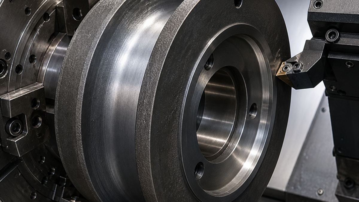
English: AISI 4340 Wire-Rope Sheave CNC Tool Selection for U-Groove Profile and Bearing Bore
The decisive tooling problem on an AISI 4340 wire-rope sheave is not simply turning a large groove. The U-groove centreline, two bearing seats and side-face runout must all refer to one axis after the quenched-and-tempered forging is unclamped. A rough-bore-first route, an expanding mandrel, supported round-carbide profiling inserts and a separate precision boring head make that relationship controllable in this hypothetical case.
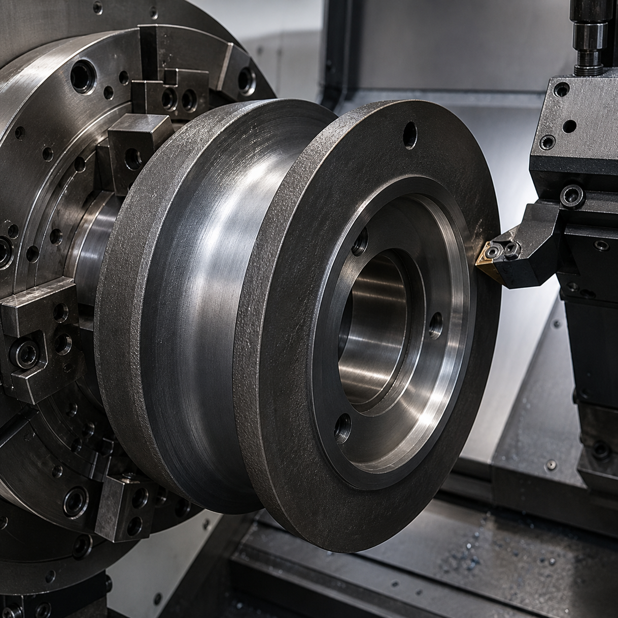
Build the drawing around the rope path
The sheave is Ø420 mm overall and 58 mm wide. Datum bore A is Ø100 H7 with two Ø118 H8 × 12 mm bearing counterbores; side face B controls axial location, and the lubrication cross-hole defines clock datum C. The rope groove has a 13.0 ±0.05 mm root radius, 25.8 ±0.08 mm opening, 22.0 ±0.10 mm depth and Ra 1.6 µm. Groove centre offset from B is 29.00 ±0.04 mm, groove radial runout to A is 0.040 mm, and each side face must run within 0.030 mm to the bearing axis.
The material note for this route is AISI 4340 quenched and tempered to a hypothetical 32–36 HRC before final machining. Hardness uniformity and forging scale are checked before committing the finishing edges. Any magnetic-particle or other safety-critical examination remains governed by the product specification; it is not invented by this machining example.
Cutting sequence matched to radial load
| Operation | Tool package | Load-management rationale |
|---|---|---|
| Forged faces and rim roughing | CNMG 120412 ISO-P25 CVD TiCN/Al2O3 carbide, heavy chipbreaker, R1.2, Capto C8 holder | The strong edge removes scale at stable depth. A sharp PVD finishing insert would chip before reaching uniform material. |
| Prebore A | Ø80 indexable carbide drill with four ISO-P30 inserts, 2×D body, followed by a twin-cartridge rough-boring head with R0.8 inserts | Balanced cutting leaves 0.35 mm radial stock. Single-point deep boring at this stage would amplify forging eccentricity. |
| Side faces B and opposite face | WNMG 080408 ISO-P15 CVD carbide with 1.5 mm wiper flat, neutral lead, rigid face-turn holder | The wiper holds Ra 1.6 µm at useful feed; alternating light passes equalize residual stress before mandrel mounting. |
| U-groove volume roughing | RCMT 1204 round ISO-P25 PVD-AlTiN carbide, positive ground chipformer, R6 circular edge, reinforced top-clamp holder | Programmed copy turning spreads contact around the round insert. A full-width 25.8 mm form tool would create excessive radial force and trap chips. |
| Groove semifinish | RCGT 1003 precision-ground positive carbide, fine-grain P20 substrate, AlTiN, 6 µm edge hone, R5 profile, damped modular holder | Smaller contact arc resolves both flanks and root with 0.15 mm stock. A negative round insert would push the rim away from A. |
| Groove finish | Two matched RCGT 0803 PVD-AlCrN carbide inserts, R4, polished rake, 4 µm hone; one dedicated to left flank/root and one to right flank/root | Splitting the finish limits engagement and lets wear compensation preserve the 13.0 mm root radius. One broad custom form insert is rejected for force and chatter. |
| Ø100 H7 and Ø118 H8 seats | Adjustable two-edge fine-boring head with ISO-P10 cermet-grade carbide cartridges, R0.2 and wiper land, short HSK-A100 arbor | The bore and counterbores are corrected on the same axis. A long reamer cannot independently correct two bearing seats. |
| Ø6 lubrication cross-hole and entry break | Ø6 three-flute through-coolant solid-carbide drill, 140° split point, AlTiN, 5×D; Ø8 four-flute 90° carbide chamfer mill | Through coolant clears the radial chip column. A pecking HSS drill would repeatedly rub the 32–36 HRC wall. |
| Internal cross-hole breakout | Ø10 four-tooth PVD-carbide reverse chamfer head, 45°, slim modular shank | It removes the bore-side lip without hand grinding near the bearing seat. |
Datum transfer from jaws to the finished bore
In the first setup, three soft jaws grip a qualified forged band. Both faces are alternately skimmed, the rim is roughed, and A is prebored while 0.35 mm remains. The sheave is unclamped for a thermal and stress pause. A second setup locates on the semifinished bore with a long expanding mandrel and pulls B against three axial pads; clamp pressure is qualified by comparing bore roundness before and after release.
The U-groove is opened in radial layers with the RCMT insert. Each path starts on a flank and exits away from the root so chips do not pack at the lowest point. Semifinish leaves 0.15 mm normal stock across the profile. Finish uses matched left and right inserts in alternating passes; the root is blended only after both flank angles and opening width are in tolerance. Constant surface speed is capped at the groove root to maintain torque margin.
Coolant jets enter from both sides of the groove and a lower nozzle clears the root. A repeating waviness at the sheave’s natural frequency, notch wear at the maximum contact line, loss of opening width or a load spike in the root triggers tool replacement. The finishing insert is never used to erase a roughing chatter band because that transfers an unknown profile error into the final radius.
Inspection follows the bearing axis
A bore gauge and roundness instrument qualify Ø100 H7 and both counterbores. On a calibrated inspection arbor, a scanning probe measures groove radius, opening and centre offset while a radial indicator records runout through 360°. Side faces are checked to the same arbor, and a borescope confirms the internal cross-hole edge. Surface roughness is sampled on both flanks and the root because a single accessible trace can miss tool pull-off.
Why machine the wire-rope groove after establishing the bore?
The expanding mandrel makes the bearing axis the machining axis, so groove runout is controlled directly rather than inherited from the rough forging OD.
Should a full-profile form tool finish the U-groove?
Not in this route. Splitting the left flank, root and right flank across supported round inserts reduces radial force and allows profile compensation.
How is chatter detected on a large 4340 sheave?
Combine spindle-load and vibration trends with a profile scan; periodic waviness or a load peak at the root is a tool-and-stability signal, not a surface to polish away.
Related guidance: fixture and chatter control and reading carbide wear signatures.
中文: AISI 4340钢丝绳滑轮配刀:U形绳槽与轴承孔
AISI 4340钢丝绳滑轮的关键不是单纯车一个大槽,而是让U形绳槽中心、两个轴承座和侧面跳动在调质锻件释放后仍共用一条轴线。本假想案例先建立半精轴承孔,再以胀芯转移基准,用有支承的圆刀片分段成形绳槽,最后用独立精镗头校正孔系。
围绕绳索轨迹读图
滑轮外径Ø420 mm、总宽58 mm。基准孔A为Ø100 H7,两侧有Ø118 H8×12 mm轴承沉座;侧面B控制轴向,润滑横孔为角向C。绳槽根圆弧R13.0 ±0.05 mm,开口25.8 ±0.08 mm,深22.0 ±0.10 mm,Ra 1.6 µm。槽中心距B为29.00 ±0.04 mm,槽对A径跳0.040 mm,两个侧面对轴承轴线端跳0.030 mm。
本路线假定AISI 4340已调质至32–36 HRC后精加工。投入精刀前检查硬度均匀性和锻造皮;磁粉或其他安全检验必须按产品规范执行,本案例不擅自编造验收要求。
按径向负载安排的配刀表
| 工序 | 刀具组合 | 负载管理理由 |
|---|---|---|
| 锻件端面和轮缘粗车 | CNMG 120412 ISO-P25 CVD TiCN/Al2O3硬质合金,强断屑、R1.2,Capto C8刀柄 | 强刃在稳定切深下去锻造皮;锋利PVD精刀在均匀材料出现前会崩。 |
| A孔预加工 | Ø80四刀片ISO-P30可转位硬质合金钻,2×D;随后双刀夹粗镗头,R0.8 | 平衡切削并留0.35 mm径向余量;此时单刃深镗会放大锻件偏心。 |
| B面及对侧面 | WNMG 080408 ISO-P15 CVD硬质合金,1.5 mm修光刃,中性主偏,刚性端车柄 | 修光刃在有效进给下保持Ra 1.6 µm,两侧交替轻切平衡残余应力。 |
| U槽体积开粗 | RCMT 1204圆形ISO-P25 PVD-AlTiN硬质合金,正角断屑,R6圆刃,增强上压刀柄 | 仿形车让接触点沿圆片移动;25.8 mm满宽成形刀径向力过大且夹屑。 |
| 绳槽半精 | RCGT 1003精磨正角细晶P20硬质合金,AlTiN、刃钝6 µm、R5,减振模块柄 | 较小接触弧在两侧和槽底均留0.15 mm;负前角圆刀会推开轮缘。 |
| 绳槽精车 | 两片配对RCGT 0803 PVD-AlCrN硬质合金,R4、抛光前刀面、刃钝4 µm;分别负责左侧/槽底和右侧/槽底 | 分刀减少包络接触,并可补偿R13.0;拒绝径向力大、易颤的宽成形刀。 |
| Ø100 H7和Ø118 H8 | 可调双刃精镗头,ISO-P10金属陶瓷级硬质合金刀夹,R0.2修光刃,短HSK-A100柄 | 在同轴上分别补偿孔和两个座,长铰刀不能独立修正各直径。 |
| Ø6润滑横孔 | Ø6三刃AlTiN内冷整体硬质合金钻,140°、5×D;Ø8四刃90°倒角刀 | 内冷排出径向长孔屑,HSS啄钻会在32–36 HRC孔壁反复擦削。 |
| 横孔内侧突破 | Ø10四齿PVD硬质合金45°反倒角头,细模块杆 | 不在轴承孔附近手工砂磨。 |
从软爪向成品孔转移基准
第一装夹用三软爪夹合格锻造带,两个侧面交替轻切,粗轮缘并将A预留0.35 mm。完全松夹恒温和释放后,第二装夹用长胀芯定位半精A,B靠三处轴向垫块。通过释放前后圆度差限定胀紧压力。
RCMT按径向层打开U槽,每条路径从侧壁进入并离开槽底,避免最低点夹屑。半精按法向均留0.15 mm。左右精刀交替完成两侧,只有开口和侧角合格后才融合槽底;恒线速在根部设转速上限,保留扭矩裕量。
两侧冷却喷嘴对准切削点,下喷嘴清槽底。与滑轮固有频率一致的波纹、最大接触线缺口磨损、开口缩小或槽底负载尖峰都结束刀具寿命。不能用精刀强行抹掉粗车颤纹,否则未知轮廓误差会被带入R13。
沿轴承轴线检验
内径表和圆度仪验证Ø100 H7及两个沉座。滑轮装在校准检验芯轴上,扫描测头测槽半径、开口和中心偏置,指示表连续记录360°径跳;两侧端跳也对同一芯轴测量。内窥镜检查横孔突破边,两侧槽壁和槽底分别测粗糙度。
为什么先建立轴承孔再加工绳槽?
胀芯把轴承轴线直接变成加工轴线,槽径跳不再继承毛坯外圆偏心。
U槽是否适合用满轮廓成形刀一次精车?
本路线不采用。将左侧、槽底和右侧分给有支承的圆刀片,可减径向力并补偿轮廓。
大型4340滑轮怎样识别颤振?
把主轴负载、振动趋势和轮廓扫描结合;周期波纹或槽底负载峰是稳定性信号,不能靠抛光掩盖。
参考:夹具与颤振控制、硬质合金磨损特征判断。
Français: Outils pour réa AISI 4340 : gorge en U et alésage
Sur un réa en AISI 4340, la gorge en U, les sièges de roulement et les faces doivent partager le même axe après desserrage. La gamme crée d’abord l’alésage, transfère la référence sur mandrin expansible, puis répartit le profil entre plusieurs plaquettes rondes soutenues.
Le chemin du câble structure le plan
Le réa fait Ø420 × 58 mm. A vaut Ø100 H7 avec deux logements Ø118 H8×12 mm; B fixe l’axial et le trou de graissage donne C. La gorge impose R13,0 ±0,05 mm, ouverture 25,8 ±0,08 mm, profondeur 22,0 ±0,10 mm et Ra 1,6 µm. Son centre est à 29,00 ±0,04 mm de B, battement radial 0,040 mm; les faces battent à 0,030 mm.
La gamme suppose un 4340 trempé-revenu à 32–36 HRC. Dureté et peau sont vérifiées; les contrôles de sécurité restent ceux de la spécification produit.
Table outil-charge
| Opération | Outil | Gestion de charge |
|---|---|---|
| Forge brute | CNMG 120412 P25 CVD TiCN/Al2O3, brise-copeau fort, R1,2, Capto C8 | Arête robuste dans la calamine. |
| Pré-alésage A | Foret indexable Ø80 à quatre plaquettes P30, puis tête deux cartouches R0,8 | Coupe équilibrée, réserve radiale 0,35 mm. |
| Faces | WNMG 080408 P15 CVD, plan wiper 1,5 mm | Ra 1,6 µm et passes alternées. |
| Ébauche U | RCMT 1204 P25 AlTiN positif, R6, serrage supérieur | Copiage réparti; pas d’outil forme de 25,8 mm. |
| Semi-finition | RCGT 1003 P20 AlTiN, arête 6 µm, R5, barre amortie | 0,15 mm normal et faible poussée. |
| Finition | Deux RCGT 0803 AlCrN R4, coupe polie 4 µm, dédiées gauche et droite | Engagement divisé et R13 compensable. |
| A et Ø118 | Tête d’alésage deux arêtes P10, R0,2 wiper, HSK-A100 court | Correction indépendante des sièges. |
| Graissage Ø6 | Foret carbure AlTiN à trois lèvres, 140°, 5×D, arrosage interne; chanfrein Ø8 | Évacuation dans 32–36 HRC. |
| Sortie interne | Tête arrière carbure Ø10, quatre dents, 45° | Pas de meulage près du siège. |
Transfert vers A
Les mors doux ébauchent faces, jante et A avec 0,35 mm. Après libération, un mandrin long porte A et B touche trois plots; la pression est qualifiée par la rondeur libre. La gorge est ouverte par couches. La semi-finition laisse 0,15 mm normal, puis les plaquettes gauche et droite alternent avant le raccord du fond.
Deux jets latéraux et un jet bas évacuent les copeaux. Ondulation périodique, usure en entaille, fermeture de l’ouverture ou pic de charge retirent l’arête.
Mesure et FAQ
Alésomètre, rondimètre et arbre étalon contrôlent A, les logements, le profil, le décalage et les battements. Le borescope vérifie le trou; rugosité des deux flancs et du fond est mesurée.
Pourquoi usiner la gorge après A?
Le mandrin transforme l’axe de roulement en axe machine.
Faut-il un outil de forme complet?
Non ici: deux plaquettes rondes réduisent la poussée et permettent la compensation.
Comment détecter le broutage?
Par charge, vibration et scan de profil, pas par une simple inspection brillante.
Voir la maîtrise du broutage et les signatures d’usure.
Русский: Инструмент для шкива 4340: канавка и отверстие
У шкива из AISI 4340 U-канавка, посадки подшипников и торцы должны иметь одну ось после освобождения. Сначала создают отверстие, затем переносят базу на разжимную оправку и делят профиль между опорными круглыми пластинами.
Траектория каната задаёт чертёж
Размер шкива Ø420 × 58 мм. A — Ø100 H7 с двумя посадками Ø118 H8×12 мм; B задаёт ось, смазочное отверстие — C. Канавка имеет R13,0 ±0,05 мм, раскрытие 25,8 ±0,08 мм, глубину 22,0 ±0,10 мм и Ra 1,6 мкм. Центр расположен 29,00 ±0,04 мм от B, радиальное биение 0,040 мм, торцы 0,030 мм.
Маршрут предполагает закалённый и отпущенный 4340, 32–36 HRC. Твёрдость и окалина проверяются; контроль безопасности задаёт спецификация изделия.
Инструмент и радиальная сила
| Операция | Инструмент | Причина |
|---|---|---|
| Грубая поковка | CNMG 120412 P25 CVD TiCN/Al2O3, сильный стружколом, R1,2, Capto C8 | Прочная кромка снимает окалину. |
| Предварительное A | Индексное сверло Ø80 с четырьмя P30 и двухкассетная головка R0,8 | Баланс и припуск 0,35 мм. |
| Торцы | WNMG 080408 P15 CVD, wiper 1,5 мм | Ra 1,6 мкм и чередование сторон. |
| Черновая U | RCMT 1204 P25 AlTiN, положительная, R6, верхний прижим | Копирование без широкой формы. |
| Получистовая | RCGT 1003 P20 AlTiN, кромка 6 мкм, R5, демпфированная оправка | Припуск 0,15 мм и малая сила. |
| Чистовая | Две RCGT 0803 AlCrN R4, полированные, 4 мкм, левая и правая | Разделённый контакт и коррекция R13. |
| A и Ø118 | Двухлезвийная головка P10, R0,2 wiper, короткая HSK-A100 | Раздельная коррекция посадок. |
| Смазка Ø6 | Трёхзубое AlTiN-сверло, 140°, 5×D, внутренняя СОЖ; фаска Ø8 | Вывод стружки из 32–36 HRC. |
| Внутренний выход | Обратная карбидная головка Ø10, четыре зуба, 45° | Без ручного шлифования посадки. |
Перенос базы
Мягкие кулачки черновят торцы, обод и A с 0,35 мм. После освобождения длинная оправка несёт A, а B касается трёх точек; давление проверяют по свободной круглости. Канавку открывают слоями, оставляют 0,15 мм по нормали и чередуют левую и правую пластины до сопряжения дна.
Два боковых и нижнее сопло выводят стружку. Периодическая волна, выемочный износ, сужение раскрытия или пик нагрузки прекращают ресурс.
Измерение и FAQ
Нутромер, кругломер и калиброванная оправка проверяют A, посадки, профиль, смещение и биение. Эндоскоп смотрит выход отверстия; Ra измеряется на обоих склонах и дне.
Почему канавка следует после A?
Разжимная оправка делает ось подшипника осью станка.
Нужна ли полная фасонная пластина?
Нет: две круглые пластины уменьшают силу и дают компенсацию.
Как найти вибрацию?
Совместить нагрузку, спектр и скан профиля.


