English: Indexable Plunge Milling Inserts for a Deep 316L Open Pocket
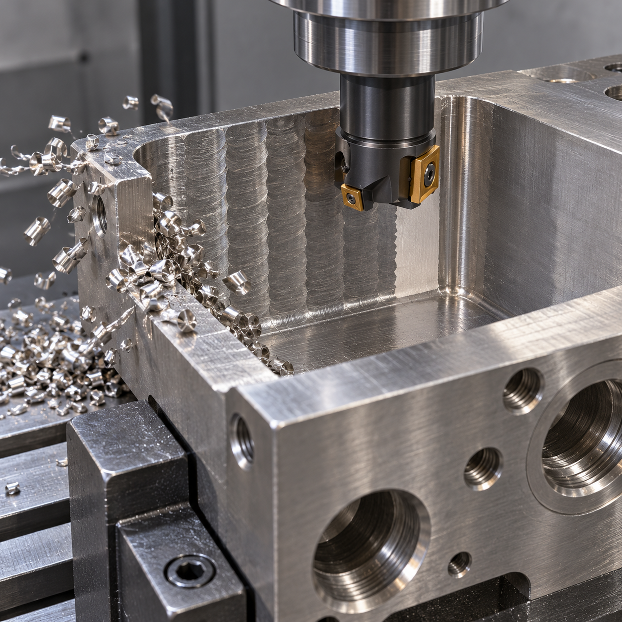
Plunge milling is a candidate when a deep pocket makes radial roughing unstable, provided the drawing offers an open approach and a way to evacuate chips. It is not permission to drive any indexable face cutter into solid metal. Our hypothetical 316L fixture has a 70 mm-deep pocket open on one side, a 45 mm mouth and R6 internal corners. The aim is to rough with mainly axial feed, then hand over a measured stock envelope to dedicated finishing tools.
Axial thrust does not make plunge feed interchangeable with lateral high-feed feed. Use the three-route cutter comparison to qualify the entry and remaining stock before considering a shared cutter body.
Draw the entry and withdrawal before the plunge pattern
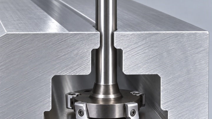
Locate the fixture on its machined bottom and side references, with clamps on solid margins. Support the floor against axial thrust while preserving coolant and chip exit. Model the complete holder, neck and cutter over the full 70 mm reach. A tool whose cutting diameter enters the mouth can still collide at its neck or holder. The first stroke approaches from the open edge; closed-area starts require a separately engineered entry, not an assumed drilling capability.
| Pocket element | Proposed carbide tooling | Reject when |
|---|---|---|
| Bulk pocket stock | 25 mm indexable body explicitly approved for plunge milling, with ISO-M-capable tough grade and positive chip-forming geometry | Axial entry, maximum lateral step or required reach is not documented |
| Scallops and wall reserve | 12 mm four-flute variable-pitch carbide end mill with relieved neck and stainless-suitable PVD coating | Remaining cusps force uncontrolled full-width contact |
| Floor finish | Shorter-reach floor tool where access permits, or qualified flat-ended carbide cutter | The plunge rougher leaves an unaccounted floor shape |
| R6 corner and mouth edges | 10 mm carbide rest tool plus separate two-flute chamfer tool | Corner blend or edge break would consume the functional wall |
Overlap is a cutting limit, not just a CAM slider
Choose the complete plunge-capable insert/body combination; CoroMill 210 is one system reference, not a claim that every size supports this reach. Use the manufacturer’s effective tooth count and plunge-feed data rather than the lateral high-feed recipe. A tough carbide substrate limits interrupted-edge damage; avoid an unnecessarily large hone that rubs on thin residual stock. Coating and coolant practice must suit the certified 316L condition.
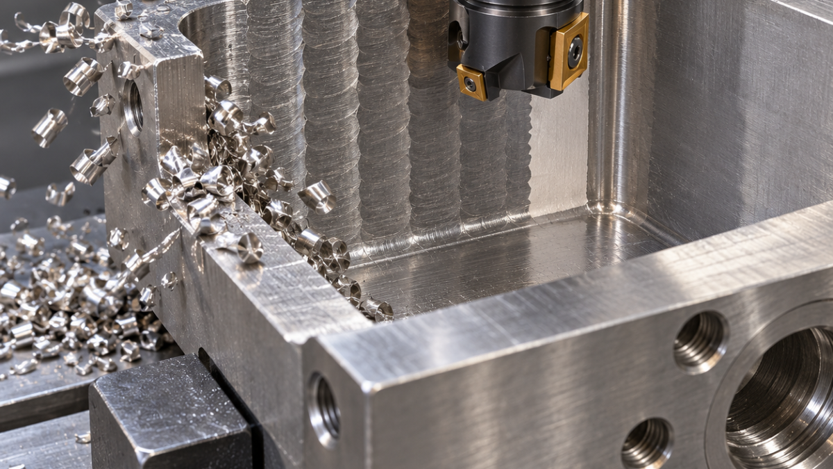
Progress inward from the opening with a lateral step inside the assembly’s limit. Simulate residual cusps, floor allowance and collisions. At depth, separate from the loaded wall by the approved escape motion before retracting; a blind rapid straight up can drag the edge over springback or trapped chips. Keep chips moving out of the open side with verified coolant delivery. Do not let repeated small, rubbing cuts work-harden the same scallop.
The rougher must leave a finishable pocket
Measure the tallest residual ridges before introducing the smaller end mill. Rest-machine them with controlled engagement; then semi-finish and finish the walls from a uniform allowance. A long four-flute tool is chosen for balance between edge support and chip space, not because more flutes always raise output. Use a low-runout holder with adequate gripping length and the shortest practical extension. Qualify speed and feed on the actual machine; no fixed metal-removal-rate claim is made here.
The drawing’s hypothetical wall profile tolerance is 0.05 mm and its floor finish Ra 1.6 µm. Inspect wall coordinates at different depths, corner blends, floor height and texture independently. Check edge wear, depth-of-cut notching and insert-seat damage after the first strokes. Any increase in recutting noise or chip packing calls for stopping and clearing the cause, not simply lowering feed into a rubbing regime.
Questions at the programmer’s desk
Can the same tool drill the first closed hole? Only if the exact assembly explicitly permits that operation; this case starts at an open side. Will plunge milling finish the floor flat? Do not assume so: model the tip geometry and reserve a separate finishing operation.
The long-edge shoulder case shows the alternative when lateral engagement is stable. Before choosing either route, check the deep-pocket reach and chip-evacuation guidance.
The later solid-carbide wall pass needs its own engagement-based cutting parameters; the plunge rougher’s axial feed must not be reused as the end mill’s lateral feed.
Tool-system reference; the workpiece and inspection examples above are hypothetical.