English: LNKX Side-and-Face Inserts for Open-Slot Width and Parallelism
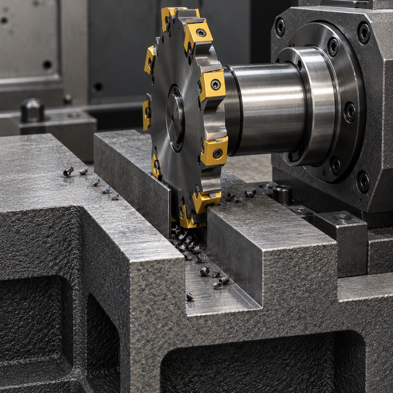
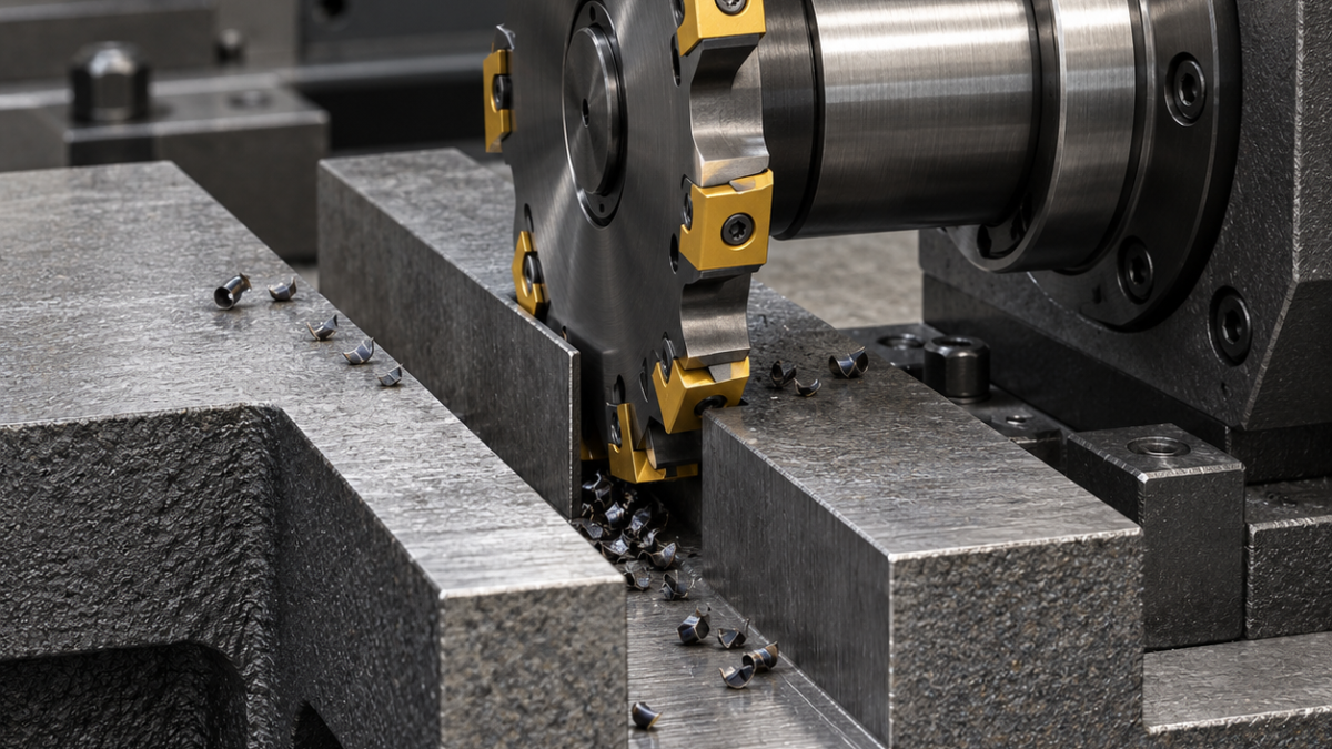
A side-and-face cutter can establish both sides of an open slot in one traverse, but the slot is generated by the assembled cutting envelope, not the nominal thickness printed on the disc. In this hypothetical EN-GJS-500-7 guide block, a 12.00–12.04 mm through slot is 32 mm deep and its cheeks must remain parallel within 0.03 mm. An LNKX-equipped system is a candidate only when the chosen cutter configuration supports that width and depth.
Start at the arbor, not at the insert box
Check the drawing’s open entry and exit against the cutter outside diameter, hub diameter, spacers and support bearing. Depth is limited by hub interference as well as tooth reach. Clamp the block on a machined base with a side stop, leaving the exit supported but clear of the disc. A long unsupported arbor can produce a tapered slot despite correct individual insert settings.
| Required surface | Tool choice | Verification |
|---|---|---|
| Base A | Short positive-carbide face mill before slotting | Base seating without cast-skin rocking |
| Slot cheeks and floor | Candidate 100 mm side-and-face disc with approved LNKX carbide inserts and staggered cutting arrangement | Actual cutting width, side-edge runout and hub clearance |
| Final cheek correction | Approved adjustable cartridge setting or separate short carbide side-finishing tool | Never force a fixed-width disc beyond its adjustment range |
| Open slot lips | Small two-flute carbide chamfer mill | Controlled break without increasing functional width |
Feed belongs to the complete tooth arrangement
Select a tough cast-iron carbide grade and coating suitable for intermittent contact; a stronger corner may survive skin, but excessive rounding raises force at the cheeks. Use the exact insert handedness and seat specified by the disc maker. Count the effective teeth for the relevant surface when calculating feed: alternating side cutters do not necessarily present every tooth to each cheek. Obtain pitch, speed and chip-load limits from the actual assembly.
Traverse with steady engagement and clear chips away from the exiting tooth. For a wide tolerance window the approved disc may rough and finish in one pass; here leave measured side stock if the assembled width cannot directly meet the 40 µm band. Do not assume a repeat pass removes only one cheek. Use the facility’s cast-iron dust and coolant practice consistently; an uncontrolled spray change can alter thermal conditions and chip recutting.
A plug gauge can conceal a wedge
Measure width near both ends and at the top and bottom. Inspect cheek parallelism, floor depth and a hypothetical Ra 3.2 µm requirement independently. Monitor axial edge displacement, arbor fretting and corner breakout; stop before a cracked insert damages the opposite cheek.
Slotting questions
Can spacers correct all width errors? Only inside an adjustable cutter’s documented setup range. Why does the slot widen at the exit? Check released arbor deflection and exit support before changing the insert grade.
A closed undercut needs the different access logic in the indexable T-slot case. The milling-direction guide helps choose entry forces relative to the stop.
Tool-system reference; the workpiece and inspection examples above are hypothetical.