English: C17200 Probe-Card Guide Plate CNC Tool Selection for 0.18 mm Hole Array
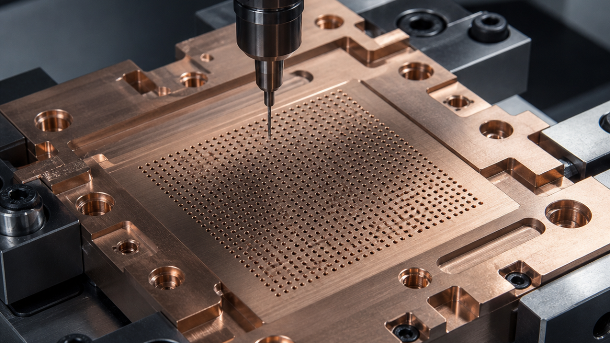
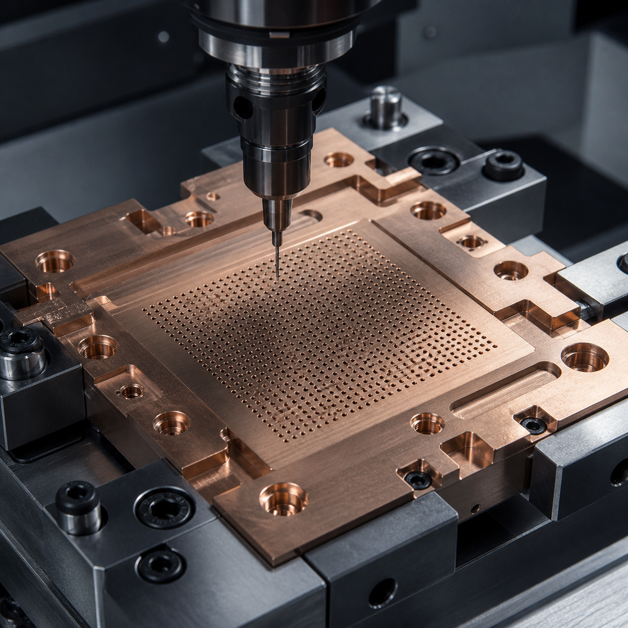
For a C17200 probe-card guide plate, the search intent is practical: select tools that can hold a Ø0.18 mm hole array on pitch without smearing the exits or warping the 2.2 mm plate. The workable answer is a short polished microdrill in an ultra-low-runout holder, a separate shallow entry-form tool, and a bonded carrier that stays attached through the last hole. This hypothetical case treats drilling order, heat, and tool-change limits as drawing decisions rather than afterthoughts.
Reading the array as an error map
Datum A is the lapped lower face; ground rails B and C establish rotation. The active field contains 420 through holes at 0.50 mm pitch. Each is Ø0.180 +0.006/0 mm with a Ø0.32 × 0.08 mm entry relief, true position Ø0.012 mm to A|B|C, and a minimum 0.31 mm land between adjacent entries. Overall thickness is 2.20 ±0.015 mm, A flatness is 0.020 mm free state, and neither a rolled exit burr nor copper smeared into the bore is acceptable.
Age-hardened C17200 combines higher strength than free-cutting copper with adhesive chip behaviour. The plan therefore separates face cutting, array location, entry relief, and release. Any production route also needs a documented exposure assessment and appropriate capture of beryllium-containing chips and mist; this article does not replace site-specific industrial-hygiene controls.
Feature-to-tool selection by error source
| Drawing feature | Specified carbide tool and holder | Decision and rejected alternative |
|---|---|---|
| A face and carrier pads | Ø6 three-flute uncoated micrograin carbide, polished 38° helix, R0.10, 5 µm edge hone, short hydraulic chuck | The sharp polished edge limits built-up material. A thick general-purpose TiAlN coating is rejected because its rounded edge tends to rub this copper alloy. |
| B-C locating rails | Ø2 four-flute ZrN-coated carbide end mill, 35° variable pitch, 4 mm reach, shrink-fit holder | ZrN reduces adhesion while four flutes stabilize the finishing cut; the reach is kept only as long as the rail requires. |
| Ø0.18 through-hole array | Ø0.18 two-flute polished carbide microdrill, 130° split point, 0.45 mm flute length, minimal edge prep, precision shrink collet with runout verified at the point | A 0.30 mm flute length is too short for breakthrough; a longer 1.0 mm drill loses column stiffness. Laser drilling is not substituted because the drawing controls a mechanically finished bore and exit condition. |
| Ø0.32 entry relief | Ø0.30 two-flute uncoated carbide drill mill, 120° included point, programmed 0.08 mm depth, ultra-precision collet | A combined step drill would enlarge the entry every time microdrill wear changes; separating the relief preserves the Ø0.18 tool’s short geometry. |
| Two Ø2 H6 datum bores | Ø1.85 coolant-fed carbide drill followed by Ø2 six-flute cermet-compatible carbide reamer, left-hand slow spiral, 4 µm hone | The reamer follows a stable pilot and produces size; interpolation with the Ø2 mill is rejected because tool runout would print directly into the datum. |
| M2 mounting threads | Ø1.60 polished carbide drill then Ø1.25 three-flute ZrN carbide thread mill, single-form profile, hydraulic holder | Thread milling keeps a broken tool recoverable and permits pitch-diameter compensation; a roll tap would impose unwanted forming load on the thin plate. |
| Perimeter and 0.05 mm edge break | Ø3 three-flute ZrN end mill for contour; Ø2 four-flute 90° polished carbide chamfer mill | The controlled chamfer is cut before release. Hand brushing is rejected because it can drag metal over the micro-hole mouths. |
Drilling sequence, carrier and tool-life gate
The blank is stress-relieved, both broad faces are skimmed with 0.04 mm stock remaining, and the lower face is bonded to a ground ceramic carrier beyond the finished outline. A and the datum rails are finished first. The array is divided into twenty-one 20-hole cells; machining alternates diagonally between cells so local temperature and clamp load do not accumulate in one corner. Each microdrill entry is single-feed after a short dwell-free approach, with through-exit support from a replaceable backing foil.
Runout is measured at the drill point and capped at 0.0015 mm for this route. Holes 1, 20 and 21 form an initial capability gate: optical position, pin acceptance, exit image and spindle-load signature must agree before the remaining cells run. A rise in load, a continuous feather at the exit, or more than two consecutive oversize relief images retires the drill. Clean low-viscosity fluid and point extraction remove chips; recutting loose copper is not accepted.
Free-state inspection and practical FAQ
While bonded, a vision CMM verifies B-C and the entry-centre map; calibrated optical pin methods and a qualified air-flow correlation sample the Ø0.18 bores. White-light measurement checks entry depth and land width. After controlled debonding and cleaning, the plate rests for thermal equalization before A flatness, thickness, and selected true positions are repeated. This separates machining accuracy from carrier restraint.
Which tool is best for drilling 0.18 mm holes in C17200?
A stub, polished two-flute carbide microdrill with a thinned 130° point and point-level runout verification is preferred; the qualified flute length should only exceed plate thickness and backing penetration.
Why not use one step drill for the hole and entry relief?
Separate tools keep the fragile Ø0.18 drill short and allow relief depth to be corrected without changing the guide bore.
How is burr control verified across hundreds of holes?
The process uses mapped inspection cells, exit images and load trends rather than relying on an end-of-batch visual sample.
Related guidance: micro-tool breakage prevention and carbide-holder runout control.
中文: C17200铍铜探针卡导向板配刀:Ø0.18微孔阵列
这类C17200探针卡导向板的核心搜索问题,是怎样给Ø0.18微孔阵列配刀,同时守住孔距、孔口和2.2 mm薄板平面度。可执行的方案是:超低跳动短刃抛光微钻、独立入口减压刀,以及直到最后一孔完成才释放的粘接载板。钻孔顺序、热量与换刀阈值都属于图纸尺寸链的一部分。
先把孔阵列读成误差分布图
研磨下表面为A,两条磨削导轨B、C控制旋转。工作区有420个0.50 mm节距通孔,孔径Ø0.180 +0.006/0 mm,入口为Ø0.32×0.08 mm减压口,相对A|B|C的位置度Ø0.012 mm,相邻入口最小孔壁0.31 mm。板厚2.20 ±0.015 mm,释放状态A面平面度0.020 mm;出口翻边和孔内铜瘤均不允许。
时效态C17200强度高于易切铜,但仍容易粘刃。因此把面铣、孔位、入口成形和释放分成独立控制环节。生产现场还必须依据适用法规完成含铍切屑和油雾的暴露评估及捕集,本案例不能替代工厂的职业卫生方案。
按误差来源配刀
| 图纸特征 | 硬质合金刀具与刀柄 | 选择及排除理由 |
|---|---|---|
| A面和载板支承区 | Ø6三刃无涂层细晶硬质合金,38°抛光槽、R0.10、5 µm刃口,短液压刀柄 | 锋利抛光刃减少积屑;厚TiAlN通用刀刃口偏钝,容易擦铜。 |
| B、C导轨 | Ø2四刃ZrN硬质合金,35°变齿距,刃长4 mm,热缩柄 | ZrN抑制粘附,四刃提高精侧壁稳定性,伸出量只满足导轨深度。 |
| Ø0.18微孔阵列 | Ø0.18双刃抛光硬质合金微钻,130°分割钻尖、槽长0.45 mm、极小刃钝化,刀尖处测跳动的精密热缩筒夹 | 0.30 mm槽长不能可靠钻穿,1.0 mm又损失柱刚度;图纸要求机械孔壁和出口,故不以激光孔替代。 |
| Ø0.32入口减压 | Ø0.30双刃无涂层硬质合金钻铣刀,120°顶角,程序深0.08 mm | 不用组合阶梯钻,避免微钻磨损变化同时改变入口直径。 |
| 两个Ø2 H6基准孔 | Ø1.85内冷硬质合金钻+Ø2六刃硬质合金铰刀,慢左旋、4 µm刃口 | 稳定底孔后铰尺寸;用Ø2铣刀插补会把刀跳直接复制到基准孔。 |
| M2安装螺纹 | Ø1.60抛光硬质合金钻+Ø1.25三刃ZrN单牙型螺纹铣刀,液压柄 | 中径可补偿,断刀也能取出;挤压丝锥会给薄板增加成形负荷。 |
| 外形和0.05 mm倒钝 | Ø3三刃ZrN立铣刀;Ø2四刃90°抛光硬质合金倒角刀 | 释放前程序倒角,拒绝会把金属拖入微孔口的手工刷磨。 |
分区钻孔与刀具寿命门槛
毛坯消除应力后双面各留0.04 mm,再在成品轮廓外粘接研磨陶瓷载板。A面及B、C完成后,将阵列分为21个、每组20孔的单元,按对角线交替加工,避免热量集中在一个角。微钻无停顿接近后一次进给穿过,出口由可更换背衬箔支承。
本路线在钻尖实测端跳上限0.0015 mm。第1、20、21孔组成放行门:孔位、通针、出口图像和主轴负载同时合格才继续。负载抬升、连续羽状毛刺或相邻两个入口异常都触发换刀。低黏度洁净切削液配合点式抽吸,禁止二次碾切散落铜屑。
释放后复检与常见问题
粘接状态用视觉三坐标验证B-C和入口坐标图,用标定光学针法及合格的流量关联抽查孔径,白光测入口深度与孔壁。受控脱胶清洗并恒温后,再测A面、厚度和选定孔位置,使载板支承误差与加工误差分开。
C17200钻Ø0.18孔应选什么刀?
选短槽、双刃、抛光硬质合金微钻,130°薄钻尖,并在刀尖处验证端跳;槽长仅需覆盖板厚和背衬穿透量。
为什么孔和入口不用一把阶梯钻?
分刀可保持Ø0.18微钻最短,并能单独补偿入口深度,不改变导向孔。
几百个微孔怎样判断毛刺失控?
用分区出口图像、负载趋势和通针结果建立地图,而不是只在整批结束后抽看几孔。
延伸阅读:微刀具防折断、硬质合金刀柄端跳控制。
Français: Outils C17200 pour plaque guide de pointes : réseau Ø0,18
La question utile est de percer un réseau Ø0,18 mm dans une plaque-guide C17200 sans déplacer le pas, étaler la sortie ni cintrer les 2,2 mm d’épaisseur. La gamme associe un microforet court et poli, un outil distinct pour l’entrée et un support collé conservé jusqu’au dernier trou.
Le réseau devient une carte d’erreurs
A est la face rodée; les rails B et C orientent la pièce. Le champ compte 420 trous au pas de 0,50 mm, Ø0,180 +0,006/0 mm, avec entrée Ø0,32×0,08 mm et position Ø0,012 mm par rapport à A|B|C. L’épaisseur vaut 2,20 ±0,015 mm et la planéité libre 0,020 mm. Une lèvre de sortie ou du métal étalé dans l’alésage est refusé.
Le C17200 vieilli reste adhésif à l’arête. La face, le guidage, l’entrée et la libération sont donc pilotés séparément. L’atelier doit aussi valider son évaluation d’exposition et son captage des copeaux et brouillards contenant du béryllium.
Matrice locale fonction-outil
| Fonction | Carbure et porte-outil | Arbitrage |
|---|---|---|
| Face A | Ø6, trois dents, carbure micrograin non revêtu, goujures polies 38°, R0,10, arête 5 µm, mandrin hydraulique court | Coupe franche; le TiAlN épais et arrondi est écarté. |
| Rails B-C | Ø2, quatre dents ZrN, pas variable 35°, portée 4 mm, frettage | Faible collage et bonne stabilité latérale. |
| Réseau Ø0,18 | Microforet carbure poli à deux lèvres, pointe amincie 130°, goujure 0,45 mm, très faible préparation, pince de précision | La longueur couvre juste la traversée; un foret long fléchit. |
| Entrée Ø0,32 | Foret-fraise Ø0,30 à deux lèvres, pointe 120°, profondeur programmée 0,08 mm | L’entrée reste indépendante de l’usure du microforet. |
| Deux Ø2 H6 | Foret carbure Ø1,85 arrosé puis alésoir Ø2 à six lèvres, spirale gauche lente | Un contournage recopierait le faux-rond. |
| M2 | Foret Ø1,60 poli puis fraise à fileter ZrN Ø1,25, trois dents, profil unique | Diamètre compensable, sans effort d’un taraud à refouler. |
| Contour et cassé | Fraise ZrN Ø3 à trois dents, puis fraise 90° Ø2 polie | Pas de brosse qui referme les entrées. |
Cellules de perçage et seuil d’usure
La plaque est collée sur un support céramique rectifié après une préfinition laissant 0,04 mm. Les 420 trous sont répartis en 21 cellules et les cellules opposées sont alternées. Un film remplaçable soutient la sortie. Le faux-rond en pointe est limité ici à 0,0015 mm.
Les trous 1, 20 et 21 ouvrent la série seulement si position, passage de pige, image de sortie et charge broche concordent. Une charge croissante, une bavure plumeuse continue ou deux entrées anormales consécutives retirent le foret.
Mesure libre et FAQ
La vision mesure B-C et la carte des centres sur support; lumière blanche, méthodes optiques étalonnées et corrélation de débit contrôlent entrée et alésage. Après décollage et stabilisation thermique, planéité, épaisseur et positions choisies sont reprises.
Quel foret pour Ø0,18 dans le C17200?
Un carbure court, poli, à deux lèvres et pointe 130°, dont le faux-rond est mesuré à la pointe.
Pourquoi séparer l’entrée?
Pour garder le foret Ø0,18 rigide et corriger 0,08 mm sans modifier le guide.
Comment surveiller les bavures?
Par cellules, avec images de sortie, charge et passage étalonné.
À consulter : prévention de casse des micro-outils et maîtrise du faux-rond.
Русский: Инструмент C17200: микросетка Ø0,18
Практическая задача — просверлить в направляющей плате C17200 сетку Ø0,18 мм, сохранив шаг, чистый выход и плоскостность толщины 2,2 мм. Для этого нужен короткий полированный микросверло, отдельный инструмент входной разгрузки и приклеенная опора до завершения последнего отверстия.
Карта допуска сетки
Шлифованная A и направляющие B-C задают систему. В поле 420 отверстий с шагом 0,50 мм: Ø0,180 +0,006/0 мм, вход Ø0,32×0,08 мм, позиция Ø0,012 мм к A|B|C. Толщина 2,20 ±0,015 мм, свободная плоскостность 0,020 мм. Завальцованный выход и налипание в канале запрещены.
Состаренный C17200 склонен к адгезии. Поэтому плоскость, координаты, вход и отклейка контролируются раздельно. Производство обязано отдельно оценить воздействие и организовать улавливание бериллийсодержащих стружки и тумана.
Подбор инструмента по источнику ошибки
| Элемент | Карбид и держатель | Выбор |
|---|---|---|
| A | Ø6, три зуба, непокрытый микрозернистый карбид, полированные 38°, R0,10, кромка 5 мкм, короткий гидропатрон | Острая кромка не размазывает сплав; толстый TiAlN исключён. |
| B-C | Ø2, четыре зуба ZrN, переменный шаг 35°, вылет 4 мм, термопатрон | Меньше налипание и вибрация. |
| Ø0,18 | Двухзубое полированное микросверло, 130°, канавка 0,45 мм, минимальная притупка, точная термоцанга | Только необходимая длина; длинное сверло отклоняется. |
| Вход Ø0,32 | Двухзубая сверло-фреза Ø0,30, угол 120°, глубина 0,08 мм | Износ микросверла не меняет вход. |
| Ø2 H6 | Сверло Ø1,85 с подводом СОЖ и шестизубая развёртка Ø2 с медленной левой спиралью | Интерполяция перенесла бы биение. |
| M2 | Сверло Ø1,60 и трёхзубая однопрофильная резьбовая фреза ZrN Ø1,25 | Компенсация диаметра без усилия раскатки. |
| Контур | Трёхзубая ZrN-фреза Ø3 и полированная фасочная Ø2, 90° | Щётка могла бы закрыть входы. |
Шахматный порядок и ресурс
После припуска 0,04 мм пластину приклеивают к шлифованной керамике. Сетку делят на 21 ячейку по 20 отверстий и чередуют диагонально. Выход поддерживает сменная фольга. Биение в вершине ограничено 0,0015 мм.
Отверстия 1, 20 и 21 открывают серию по координате, проходу калибра, снимку выхода и нагрузке. Рост нагрузки, сплошной перистый заусенец или две аномальные входные зоны означают замену.
Свободное измерение и FAQ
Оптическая КИМ строит карту B-C; белый свет, калиброванные оптические методы и расход проверяют вход и канал. После отклейки и выдержки повторяют плоскостность, толщину и выбранные координаты.
Какое сверло выбрать для Ø0,18?
Короткое двухзубое полированное карбидное сверло 130° с измерением биения в вершине.
Почему вход делает другая фреза?
Микросверло остаётся жёстким, а глубина 0,08 мм корректируется отдельно.
Как контролируют сотни выходов?
По ячейкам, совмещая снимки, нагрузку и проходной контроль.


