English: AlSiC Power-Module Baseplate CNC Tool Selection for Thermal Flatness and Insert Bores
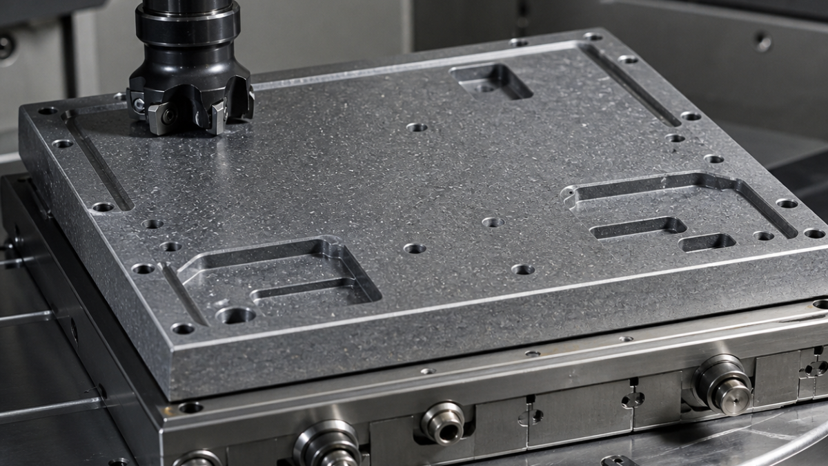
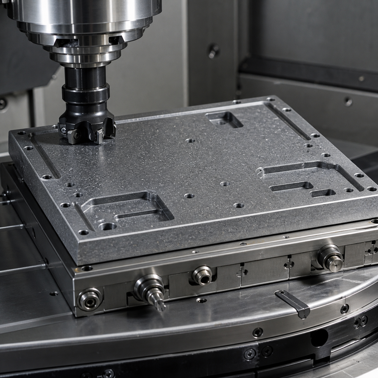
An AlSiC power-module baseplate needs a tooling split between abrasive bulk removal and the final thermal-interface face. The practical long-tail answer is to rough pockets with diamond-coated carbide, generate the broad datum with a low-runout PCD face mill, and finish insert bores with dedicated PCD sizing tools while the plate rests on defined pads. This hypothetical case keeps the 0.025 mm flatness requirement separate from clamped machine coordinates and prevents silicon-carbide particles from becoming a second cutting edge.
Functional surfaces, not just a rectangular plate
The lower thermal face A is 160 × 120 mm and must be flat within 0.025 mm after release, with Ra 0.8 µm and no isolated pull-out larger than the drawing acceptance sample. Two dowel bores B and C define module orientation. The opposite side contains four isolation pockets 2.00 ±0.03 mm deep, a 1.20 mm perimeter sealing land, twelve Ø5 H7 bores for pressed thread inserts, and four Ø6 H8 coolant-manifold locations. Remaining web thickness under a pocket is 3.00 ±0.05 mm; parallelism of the pocket floors to A is 0.030 mm.
AlSiC is an aluminium matrix loaded with hard silicon-carbide particles. The exact fraction, particle size and heat-treatment state belong on the material certificate because they change edge wear and pull-out. The route below qualifies tools against the supplied lot rather than assuming that every AlSiC grade cuts identically.
Tool card for each surface class
| Surface class | Selected cutter, edge and holder | Use limit and rejected choice |
|---|---|---|
| Stock face and outside profile | Ø12 two-flute diamond-coated fine-grain carbide end mill, 30° helix, R0.3, 18 mm flute length, balanced shrink-fit holder | The coating protects carbide from SiC abrasion while the two large gullets evacuate mixed chips. An uncoated aluminium end mill loses diameter too quickly. |
| Isolation-pocket roughing | Ø8 three-flute diamond-coated carbide, unequal pitch, R0.5, 12 mm reach, through-air hydraulic chuck | Helical entry and constant engagement keep particles moving. A high-feed insert mill is rejected because its minimum corner radius cannot protect the 1.20 mm sealing land. |
| Pocket walls and 1.5 mm internal corners | Ø3 four-flute diamond-coated carbide, 25° helix, R0.15, 7 mm flute length, ultra-short heat-shrink extension | Four supported edges finish the abrasive wall. A longer microtool would trade useful reach for runout and taper. |
| Thermal face A | Ø63 five-pocket PCD face mill, axial runout set below 0.003 mm, 0.05 mm wiper flats, HSK-A63 face-contact arbor | One light climb pass creates a consistent lay. A carbide face mill can meet size initially but its changing flank wear prints steps across 160 mm. |
| Ø5 H7 insert bores | Ø4.7 diamond-coated carbide drill, 140° point and through coolant; then Ø5 six-flute PCD-tipped straight reamer, 6 µm edge preparation, hydraulic holder | The reamer sets press-fit size after abrasive drilling. Circular interpolation is rejected because cutter wear would make twelve different diameters. |
| Ø6 H8 manifold locations | Ø5.6 PCD-veined carbide drill followed by an adjustable PCD fine-boring cartridge, R0.1, short modular head | Fine boring corrects position and diameter. A fixed reamer could follow a particle-deflected pilot. |
| Counterbores and 0.15 mm edge breaks | Ø9 three-flute diamond-coated carbide counterbore with integral pilot; Ø6 two-flute 90° PCD chamfer tool | A piloted tool controls insert-seat squareness. Abrasive hand deburring can round the sealing land and contaminate A. |
Two supports for two different questions
During pocket roughing, the blank sits on three hardened pads beneath thick regions and is restrained by low-force perimeter clamps. Floors are left 0.08 mm high, walls 0.05 mm heavy. The toolpath begins in the deepest central volume and works outward so remaining webs stay supported. The part is then released, cleaned and allowed to equalize at the inspection temperature before its natural bow is mapped.
For A finishing, the plate is inverted onto a vacuum fixture whose lands coincide with the drawing’s stiff zones; vacuum level is limited by a deflection trial rather than maximized. A PCD face-mill test strip at one edge confirms wiper height and pull-out before the full pass. Insert bores are made after A establishes Z, but pressed inserts are not installed until all machining and cleanliness checks are complete.
Dry point extraction or a validated wet-capture method must prevent abrasive chips from recirculating through the spindle and guideways. A rising spindle-load slope, loss of corner radius, gray smear on the PCD land or increasing bore thrust ends tool life. Tools are not run until catastrophic chipping because one missing edge can scratch the entire thermal face.
Inspection tied to temperature and support
A calibrated surface plate and scanning probe measure free-state A at the specified temperature. White-light metrology checks Ra and pull-out against the agreed sample; a CMM builds A-B-C, pocket depth, web thickness and bore position. Air or certified plug gauges verify the insert bores, while a low-force fixture repeats A under assembly-like support to distinguish true shape from mounting response. Results record material lot and PCD edge number so abrasive variation is traceable.
What cutter gives the best flat AlSiC thermal face?
A low-runout PCD face mill with matched wiper flats is preferred for the final broad pass; its setup must be qualified on the actual AlSiC lot.
Why not finish the insert bores by end-mill interpolation?
Diameter loss on an abrasive composite changes every interpolated hole. A dedicated PCD reamer or fine-boring head makes wear measurable and correctable.
Should AlSiC be machined dry or wet?
The choice belongs to the machine, material and exposure-control assessment. Either method must capture abrasive particulate and prevent recirculation; an open uncontrolled dust stream is not acceptable.
Related reading: PCD tool selection for aluminium systems and runout control for precision cutters.
中文: AlSiC功率模块底板配刀:热界面平面度与镶件孔
AlSiC功率模块底板必须把高磨蚀开粗和热界面精加工分开配刀。可执行方案是用金刚石涂层硬质合金开腔、低跳动PCD面铣刀完成大基准,再以专用PCD定径刀加工镶件孔,同时让板件落在图纸定义的支承区。这样0.025 mm平面度不会被夹具坐标掩盖,碳化硅颗粒也不会在成品面上二次划削。
图纸控制的是功能表面
下热界面A为160 × 120 mm,释放后平面度0.025 mm、Ra 0.8 µm,局部颗粒脱落不得超过图纸认可样板。两处销孔B、C确定模块方向。另一面有四个2.00 ±0.03 mm隔离腔、1.20 mm周边密封台、十二个Ø5 H7压入螺纹镶件孔及四个Ø6 H8冷却歧管位置。腔底最小余厚3.00 ±0.05 mm,腔底对A平行度0.030 mm。
AlSiC由铝基体和硬质碳化硅颗粒组成。实际体积分数、粒径及状态必须以材料证书为准,因为它们会改变磨损和颗粒拔出。本路线按来料批次验证,不把所有AlSiC假定为相同切削性能。
按表面类别建立刀具卡
| 表面类别 | 刀具、刃口与刀柄 | 使用理由和排除方案 |
|---|---|---|
| 毛坯面与外形 | Ø12双刃金刚石涂层细晶硬质合金,30°螺旋、R0.3、刃长18 mm,动平衡热缩柄 | 涂层抵抗SiC磨蚀,大容屑槽排混合切屑;无涂层铝用刀直径损失过快。 |
| 隔离腔开粗 | Ø8三刃金刚石涂层硬质合金,变齿距、R0.5、有效长12 mm,通气液压柄 | 螺旋进入配恒定吃刀;高进给刀圆角过大,无法保护1.20 mm密封台。 |
| 腔壁和1.5 mm内角 | Ø3四刃金刚石涂层硬质合金,25°、R0.15、刃长7 mm,超短热缩接长 | 四个有支承刃完成磨蚀侧壁,拒绝为无用伸出量牺牲跳动的长刀。 |
| 热界面A | Ø63五齿PCD面铣刀,轴向跳动调至0.003 mm以下,0.05 mm修光刃,HSK-A63端面接触刀杆 | 单次轻载顺铣形成一致纹路;硬质合金面刀磨损变化会在160 mm表面印出台阶。 |
| Ø5 H7镶件孔 | Ø4.7金刚石涂层内冷硬质合金钻,140°;随后Ø5六刃PCD直槽铰刀,6 µm刃口,液压柄 | 磨蚀钻孔后由铰刀定压配尺寸;插补会使十二孔随刀径磨损逐个变化。 |
| Ø6 H8歧管孔 | Ø5.6 PCD刃硬质合金钻+可调PCD精镗刀夹,R0.1,短模块头 | 精镗可修正颗粒引起的底孔偏移,固定铰刀只会跟孔走。 |
| 沉孔和0.15 mm倒钝 | Ø9三刃金刚石涂层带导向沉孔刀;Ø6双刃90°PCD倒角刀 | 带导向保证镶件座垂直,手工砂磨会圆化密封台并污染A面。 |
两种支承回答两种问题
腔体开粗时,毛坯落在三处厚壁下方的淬硬垫块上,周边低力限位。腔底留0.08 mm、侧壁留0.05 mm,从中央最深容积向外加工,让余下筋位持续支承。随后完全释放、清洁并在检验温度恒温,先测自然翘曲。
精A面时翻到真空夹具,真空台只在刚性区域设密封支承;真空值由挠度试验确定,不追求最大。PCD先在边缘切验证带,确认修光刃高差和颗粒拔出,再走完整一刀。A建立Z后完成镶件孔,但所有加工及清洁检验结束前不压装镶件。
无论点式干抽还是验证过的湿式捕集,都必须阻止磨粒返回主轴和导轨。负载斜率上升、圆角损失、PCD刃带发灰或钻孔推力增加都结束刀具寿命,不能等崩刃后才换刀。
把检验与温度、支承绑定
在规定温度下用校准平台和扫描测头检查A自由状态;白光对照认可样板测Ra和颗粒拔出。三坐标建立A-B-C并测腔深、底厚和孔位,气动或合格塞规测镶件孔。再用接近装配支承的低力夹具复测A,区分真实形状与安装响应。报告记录材料批号和PCD刃号。
AlSiC热界面用什么刀最容易保证平面度?
用修光刃匹配、低跳动PCD面铣刀完成最终大面,但必须在实际材料批次上先验证。
为什么镶件孔不直接用立铣刀插补?
磨蚀材料会持续缩小刀径,导致各孔尺寸顺序漂移;PCD铰刀或精镗头更容易测量和补偿。
AlSiC应该干切还是湿切?
取决于机床、材料和暴露控制评估;两者都必须有效捕集磨粒并防止循环,不能开放扬尘。
相关内容:铝基材料PCD刀具选择、精密刀具跳动控制。
Français: Outils AlSiC pour semelle de puissance : planéité et alésages
Une semelle AlSiC exige deux familles d’outils: carbure diamanté pour enlever la matière abrasive, puis PCD à faible faux-rond pour l’interface thermique. Les alésages d’inserts sont calibrés séparément pendant que la plaque repose sur des appuis définis.
Surfaces fonctionnelles du plan
La face A mesure 160 × 120 mm, avec planéité libre 0,025 mm et Ra 0,8 µm. B et C orientent le module. L’autre côté porte quatre poches profondes de 2,00 ±0,03 mm, une portée périphérique de 1,20 mm, douze alésages Ø5 H7 et quatre positions Ø6 H8. Le fond minimal vaut 3,00 ±0,05 mm et les poches sont parallèles à A à 0,030 mm.
La fraction et la taille du SiC doivent venir du certificat matière, car elles modifient usure et arrachement. Les outils sont qualifiés par lot.
Carte d’outil par surface
| Surface | Outil et montage | Limite |
|---|---|---|
| Profil brut | Ø12, deux dents, carbure diamanté, 30°, R0,3, goujure 18 mm, frettage équilibré | Le carbure aluminium non revêtu perd son diamètre. |
| Poches | Ø8, trois dents diamantées, pas inégal, R0,5, portée 12 mm, mandrin hydraulique | Engagement constant sans toucher la portée de 1,20 mm. |
| Parois et rayons | Ø3, quatre dents diamantées, 25°, R0,15, coupe 7 mm | Portée minimale contre faux-rond et conicité. |
| Interface A | Tourteau PCD Ø63 à cinq logements, faux-rond axial <0,003 mm, plats wiper 0,05 mm, HSK-A63 | Une seule passe évite les marches d’usure du carbure. |
| Ø5 H7 | Foret carbure diamanté Ø4,7, 140°, puis alésoir PCD Ø5 à six lèvres | L’interpolation dérive avec l’usure. |
| Ø6 H8 | Foret à veine PCD Ø5,6 puis tête d’alésage PCD réglable R0,1 | Corrige position et diamètre. |
| Lamage et cassé | Lameur guidé Ø9 diamanté; outil PCD Ø6 à 90° | Pas d’abrasif manuel sur la portée. |
Appuis séparés, copeaux captés
Trois plots sous les zones épaisses portent l’ébauche; les fonds gardent 0,08 mm et les murs 0,05 mm. Après libération et stabilisation, A est cartographiée. Pour finir A, le vide agit seulement sous les zones rigides et sa valeur vient d’un essai de flèche. Une bande test confirme le PCD avant la passe complète.
L’extraction sèche ponctuelle ou le captage humide validé doit empêcher le retour des particules. Charge croissante, rayon perdu, bande grise ou poussée de perçage retirent l’outil.
Contrôle et FAQ
Une plaque étalon et un palpage scanné mesurent A libre; lumière blanche, MMT et calibres contrôlent arrachement, A-B-C, épaisseurs et alésages. Le lot matière et l’arête PCD restent dans le rapport.
Quel outil pour la face thermique?
Un tourteau PCD réglé sous 0,003 mm de faux-rond axial.
Pourquoi ne pas interpoler Ø5 H7?
L’usure abrasive change progressivement le diamètre.
Usinage sec ou humide?
Seulement avec une méthode validée qui capte les particules et évite leur recirculation.
Voir les outils PCD et le contrôle du faux-rond.
Русский: Инструмент AlSiC для силовой плиты
Для плиты силового модуля AlSiC абразивную черновую обработку отделяют от тепловой поверхности. Карбид с алмазным покрытием режет карманы, PCD-торцевая фреза формирует A, а отдельные PCD-инструменты калибруют отверстия вставок на заданных опорах.
Функции чертежа
A имеет размер 160 × 120 мм, свободную плоскостность 0,025 мм и Ra 0,8 мкм. B-C задают направление. Сверху четыре кармана 2,00 ±0,03 мм, пояс 1,20 мм, двенадцать Ø5 H7 и четыре Ø6 H8. Остаточное дно 3,00 ±0,05 мм, параллельность 0,030 мм.
Доля и размер SiC берутся из сертификата: они меняют износ и вырыв. Инструмент проверяется на партии.
Карта поверхностей и резцов
| Поверхность | Инструмент | Ограничение |
|---|---|---|
| Черновой контур | Ø12, два зуба, алмазное покрытие на мелкозернистом карбиде, 30°, R0,3, длина 18 мм, термопатрон | Непокрытая алюминиевая фреза быстро теряет размер. |
| Карманы | Ø8, три зуба, алмазное покрытие, переменный шаг, R0,5, длина 12 мм | Постоянное зацепление защищает пояс. |
| Стенки | Ø3, четыре зуба, алмазное покрытие, 25°, R0,15, длина 7 мм | Минимальный вылет снижает конус. |
| A | PCD-фреза Ø63, пять гнёзд, осевое биение <0,003 мм, wiper 0,05 мм, HSK-A63 | Один проход без ступеней износа. |
| Ø5 H7 | Алмазно-покрытое сверло Ø4,7, 140°, затем шестизубая PCD-развёртка Ø5 | Интерполяция дрейфует с износом. |
| Ø6 H8 | PCD-сверло Ø5,6 и регулируемая PCD-головка R0,1 | Исправляет координату. |
| Цековка | Направляемый алмазный карбид Ø9; фасочная PCD Ø6, 90° | Ручной абразив повредит пояс. |
Две схемы опоры
Черновая деталь лежит на трёх точках под толстыми зонами; дно оставляет 0,08 мм, стены 0,05 мм. После освобождения и выдержки картируют изгиб. При чистовой A вакуум действует только под жёсткими зонами, а его величину определяет испытание прогиба. Крайняя пробная полоса подтверждает PCD.
Точечная сухая вытяжка или проверенный мокрый сбор исключают возврат абразива. Рост нагрузки, потеря радиуса, серый след или рост осевой силы прекращают ресурс.
Измерение и FAQ
A измеряют свободно на плите; белый свет, КИМ и калибры проверяют вырыв, A-B-C, толщины и отверстия. В отчёте остаются партия и номер кромки PCD.
Чем фрезеровать тепловую плоскость?
PCD-фрезой с осевым биением менее 0,003 мм.
Почему не интерполировать Ø5 H7?
Абразивный износ постепенно меняет каждый диаметр.
Резать сухо или мокро?
Только проверенным способом с улавливанием и без рециркуляции частиц.


