English: T490 LNMT Long-Edge Inserts for Tall Steel Shoulder Milling
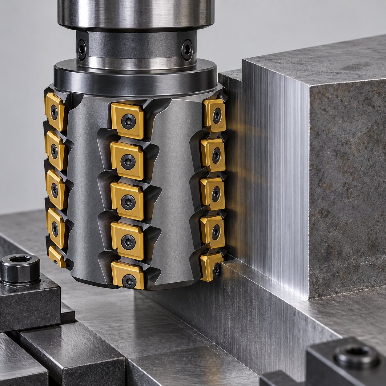
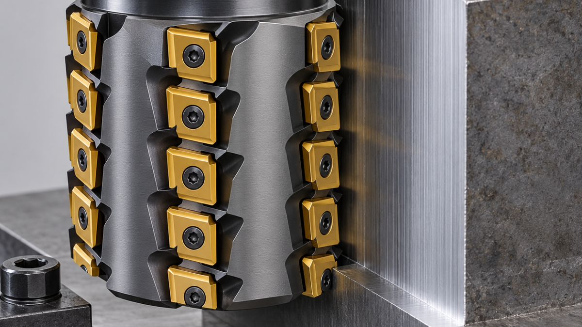
For a tall open shoulder, a tangential long-edge cutter offers a stiff core and several axial rows of carbide inserts. That does not make its roughing envelope a guaranteed finished wall. This hypothetical P20 slide block has a 60 mm-high external shoulder, an R2 floor blend and a 0.04 mm straightness requirement. The tooling question is whether a T490 LNMT-family assembly can remove the side stock without leaving row-transition errors that exceed the finishing allowance.
One wall, several cutting rows
Start with the actual prehardened material certificate and a measured stock model. The proposed blank is already seated on base A, with side stops taking cutting load rather than relying entirely on clamp friction. Put clamps over solid support outside the cutter’s exit. A nominally long cutting edge is made from overlapping insert segments; the permissible axial engagement belongs to the complete cutter, not to a single insert’s catalog depth.
| Drawing task | Candidate tool | Reason for the choice |
|---|---|---|
| 60 mm open shoulder roughing | Approximately 50 mm long-edge body, qualified T490 LNMT 13-family inserts, sufficient active row length | Tangential seating supports the insert; confirm body length, pitch, power and all-row clearance before ordering |
| Uniform wall stock | Same assembly with a measured radial cleanup pass | Remove roughing ridges without assuming every axial row cuts the same diameter |
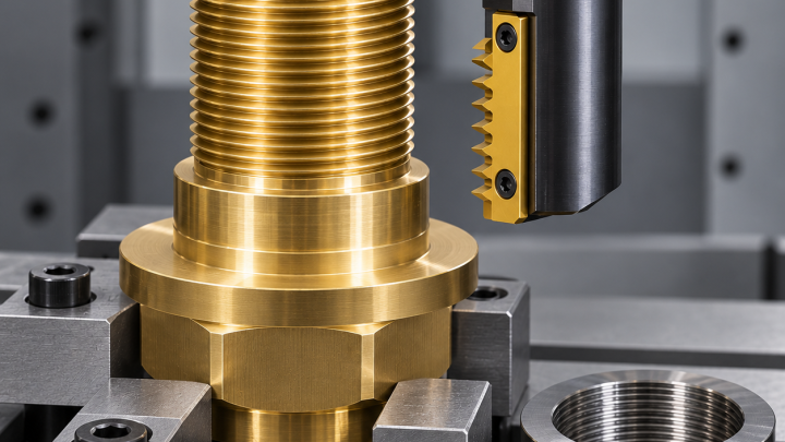
| Final wall and R2 blend | 20 mm four-flute solid-carbide corner-radius end mill, R2, short flute length with qualified relieved reach | Separate wall accuracy from rougher insert-row mismatch; do not use an unnecessarily long fully fluted tool |
| Top edge | Two-flute carbide chamfer cutter | Small controlled break after the wall is accepted |
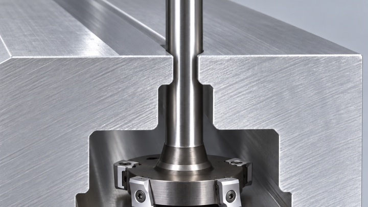
If torque or side deflection rejects this long-edge route, compare the full replacement sequence, not only a higher feed number. The high-feed, shoulder and plunge comparison includes the remaining wall-finishing duty.
Torque and chip space decide the roughing strategy
Choose a tough steel-milling carbide grade with a suitable PVD coating and a supported edge, subject to the insert supplier’s hardness range. A very sharp light-cut geometry may not survive the first interrupted edge; a heavily honed insert may raise radial force unnecessarily. Use the manufacturer’s complete assembly with every specified pocket filled. Axial insert count is not the number of teeth to put blindly into a feed formula: determine the effective circumferential teeth for the engaged zone.
Run open-side climb passes where machine condition permits, entering with a controlled arc. Compare predicted torque at the selected spindle speed with available torque, not only the motor’s nameplate power. If a full-height engagement overloads the system, reduce radial engagement or use staged axial bands with intentional overlap. A dense-pitch head is rejected when chip space or torque becomes the limiting factor. A short single-row shoulder cutter is still a valid alternative if its additional stepdowns leave a more reliable finish allowance.
The witness line is inspection data
After roughing, inspect wall stock at the insert-row junctions. Remove retained chips before the semi-finish pass, keep coolant delivery consistent and avoid dwelling against prehardened steel. Finish from measured stock with a balanced low-runout holder and verified neck clearance; long reach still needs a stability trial. If bands are necessary, locate the transition away from the functional contact zone when the drawing allows it, never by silently changing the drawing.
Check wall straightness at several heights and lengths, perpendicularity to A, the R2 blend and a hypothetical Ra 1.6 µm requirement. Record which row produces a step. A damaged pocket, chip under an insert or uneven flank wear is not corrected by a global diameter offset. Monitor corner chipping and row-specific load marks before they contaminate the finishing stock.
Questions before releasing the tool list
Does a tangential insert automatically allow full-height cutting? No; body capacity, reach, machine torque and workholding all govern it. Can one diameter correction remove every horizontal line? Not if different rows have different envelopes.
When lateral force becomes the main obstacle, compare the axial plunge-milling route for a deep open pocket. For finish-tool vibration diagnosis use the low-runout holder diagnostic guide, after checking the insert seats first.
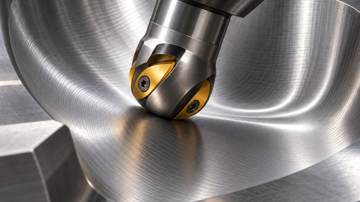
If the straight wall joins a forming surface, use the ball-nose semi-finishing stock check for the curved region; a shoulder cutter’s diameter correction does not validate a spherical contact envelope.
Tool-system reference; the workpiece and inspection examples above are hypothetical.