English: Nitinol Actuator Collet CNC Tool Selection for 0.35 mm Flexure Slots and Thin Fingers
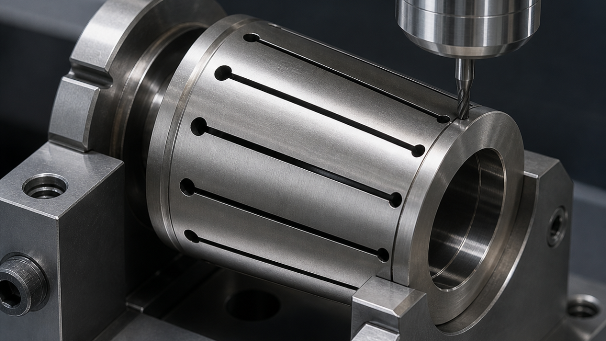
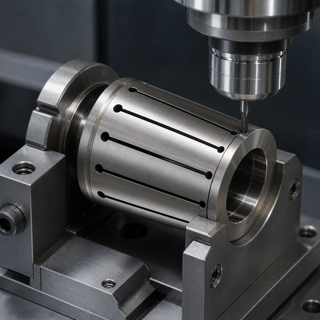
A Nitinol actuator collet with 0.35 mm flexure slots should be tooled from the failure sequence backward: first prevent finger movement, then prevent work-hardened slot walls, and only then chase the free-state bore. In this hypothetical drawing, twelve relief holes and slots create spring fingers around an Ø8 H7 bore. A supported sacrificial ring, low-hone PVD-coated carbide microtools, a neutral grooving insert and post-release probing provide a practical route without pretending that clamped dimensions equal functional dimensions.
Three states hidden in one drawing
Before slotting, datum face A, pilot diameter B and index notch C locate the sleeve. The solid state carries an Ø7.92 mm semifinished bore and a 20.00 mm outside diameter. The supported state adds twelve Ø0.80 relief holes connected to 12.0 mm-long slots, each 0.350 +0.025/0 mm, leaving fingers 1.20 ±0.025 mm wide. In the released state, bore B must be Ø8 H7, finger-tip radial spread must remain within 0.040 mm, the external retention groove is 0.80 ±0.02 mm wide, and slot walls require Ra 1.6 µm without a continuous burr.
Nitinol can work-harden and recover elastically around the cutter. The program does not use dwell or repeated rubbing passes to “clean” a slot. Each tool has a defined minimum chip thickness, entry path, maximum engagement count and inspection signature.
Failure-led feature-to-tool map
| Failure to prevent | Drawing feature and selected carbide tool | Why the competing choice is rejected |
|---|---|---|
| Bore closes after finger release | Solid-state rough bore: positive CCGT 060202 PVD-AlTiN fine-grain carbide, R0.2, 7° clearance on a short steel bar; released finish: Ø7.7 pilot then adjustable micro-boring head with a polished AlTiN carbide insert, R0.1 | A fixed Ø8 reamer would follow the distorted supported bore and cannot correct the released axis. |
| Outside diameter pushes the sleeve off axis | VCGT 110302 PVD-TiAlN carbide, sharp 6–8 µm edge preparation, R0.2, rigid Swiss-style holder | A heavily honed negative insert raises heat and radial force on the thin tube. |
| Relief holes smear or crack at breakout | Ø0.80 two-flute through-coolant carbide drill, 140° split point, AlTiN, 2.5 mm flute length, precision collet | A centre drill plus long peck cycle causes extra rubbing; laser holes are not substituted because recast and thermal effects are outside this drawing route. |
| 0.35 mm slots taper or harden | Ø0.30 three-flute necked micro end mill, AlTiN nanolayer, 25° helix, 12.6 mm reach, 4–6 µm hone, shrink-fit holder with verified 0.002 mm runout | A full-width Ø0.35 cutter has no compensation room; a slitting saw cannot follow the cylindrical index without a new fixturing error. |
| Slot floor leaves a stress raiser | Ø0.60 two-flute AlTiN carbide ball end mill, 8 mm neck, tangent blend into the predrilled Ø0.80 relief | A sharp square termination concentrates strain; the ball path blends without recutting the long slot walls. |
| Retention groove springs open | 0.80 mm neutral PVD-TiAlN carbide grooving insert, ground positive flanks, 0.05 mm corner radii, compact gang holder | A wide negative groover deflects the sleeve and masks width recovery while clamped. |
| Finger edges carry a continuous burr | Ø1.5 four-flute 45° AlTiN carbide lollipop-style back-chamfer tool, 0.03 mm programmed break, slim hydraulic holder | A rotary brush may bend fingers and smear the spring alloy; manual stones cannot maintain twelve equal edges. |
| Threaded mounting holes gall | Ø1.60 AlTiN carbide drill and Ø1.25 three-flute single-form carbide thread mill for M2, internal coolant holder | Thread milling avoids tap reversal and permits pitch-diameter compensation in a work-hardened hole. |
Sacrificial ring, one-direction slots and release
The tubular blank is supported on a precision expanding mandrel at the unslotted land; a split polymer-metal nest contacts the OD without forcing the future fingers round. A 2.0 mm sacrificial end ring remains beyond the finished tips. A, B, C, the OD, groove and relief holes are completed while the cylinder is solid. Hole position is probed before a single slot is opened.
Slots are machined in a 1-7-4-10 opposite sequence. The Ø0.30 tool enters through the Ø0.80 relief, makes a trochoidal centreline rough path leaving 0.018 mm per wall, and takes one climb-finish pass in the same axial direction for every finger. It never dwells at the closed end. High-pressure, well-directed coolant clears short chips, while maximum spindle load and acoustic signature are recorded for the first slot. A polished band, rising load, width taper or corner microchipping retires the tool before it is allowed into the next opposite pair.
After all edges are broken, the sacrificial ring is removed in two alternating arc segments so the fingers do not release at once. The part rests at the inspection temperature. Only then is the bore lightly finish-bored on a soft expanding support, using measured radial recovery rather than the supported offset.
Measurement closes the state loop
A vision system measures each slot at three axial stations and compares opposite finger widths. A low-force scanning probe builds the released bore and tip envelope; a roundness trace separates harmonic spring recovery from tool taper. Groove width is checked both on the support and free state, and white-light metrology confirms slot-wall finish and the blended relief. The machining record includes tool runout, slot order and pre/post-release dimensions so a change in material transformation behaviour is visible rather than hidden in a final pass.
What end mill should cut a 0.35 mm slot in Nitinol?
A Ø0.30 necked, low-hone AlTiN carbide micro end mill provides wall compensation and reaches the relief hole; the exact speed and chip load must be qualified to avoid rubbing.
Why keep a sacrificial ring on the finger tips?
It keeps all fingers in one cylindrical stiffness state during slotting and chamfering, then allows controlled release before final bore correction.
Can wire EDM replace micro milling for the flexure slots?
It may be a separate qualified route, but recast, heat-affected condition, corner geometry and cleaning would require their own drawing acceptance; it is not treated as an automatic substitute here.
Related guides: heat and notch-wear control in nickel alloys and selecting carbide-tool coatings.
中文: 镍钛执行器弹性夹套配刀:0.35 mm槽与薄指
镍钛执行器夹套应从失效顺序倒推配刀:先限制薄指移动,再避免槽壁加工硬化,最后才校正自由状态内孔。本假想图纸由十二个减应力孔和0.35 mm纵槽形成弹性指,包围Ø8 H7内孔。保留端部工艺环、采用小刃钝化PVD硬质合金微刀、配中性槽刀并在释放后测量,才能避免把夹紧尺寸误认为功能尺寸。
一张图纸中的三种状态
开槽前,端面A、导向外径B和索引缺口C定位。完整圆筒状态的孔先做到Ø7.92 mm、外径20.00 mm。支承状态加工十二个Ø0.80减应力孔及12.0 mm长槽,槽宽0.350 +0.025/0 mm,指宽1.20 ±0.025 mm。释放状态要求B为Ø8 H7、指尖径向散差0.040 mm以内、外卡槽宽0.80 ±0.02 mm,槽壁Ra 1.6 µm且无连续翻边。
镍钛合金会加工硬化,并在刀后弹回。程序禁止停顿,也禁止用多次无切屑的“光刀”擦槽;每把刀必须规定最小切屑厚度、进入路径、最大开槽数和失效信号。
从失效反推的特征配刀表
| 要防止的失效 | 图纸特征与硬质合金刀 | 为什么拒绝替代方案 |
|---|---|---|
| 释放后内孔收缩 | 实心态用CCGT 060202正角PVD-AlTiN细晶硬质合金,R0.2、7°后角、短镗杆粗孔;释放后用可调微镗头和R0.1抛光AlTiN刀片精B | 固定Ø8铰刀只会跟随支承状态的变形孔,不能修正释放后的轴线。 |
| 车外圆时套筒偏心 | VCGT 110302 PVD-TiAlN硬质合金,6–8 µm锋利刃钝化、R0.2,瑞士型刚性刀架 | 重钝化负前角刀会增加薄筒热量和径向力。 |
| 减应力孔突破时涂抹或开裂 | Ø0.80双刃内冷AlTiN硬质合金钻,140°分割钻尖、槽长2.5 mm,精密筒夹 | 中心钻加长啄钻会多次擦削;本路线也不把带再铸层风险的激光孔直接替代机械孔。 |
| 0.35 mm槽锥度或硬化 | Ø0.30三刃缩颈AlTiN纳米层微立铣刀,25°螺旋、有效长12.6 mm、4–6 µm刃口,热缩柄端跳≤0.002 mm | 满宽Ø0.35刀没有补偿空间;切缝锯又会引入圆周重新找正误差。 |
| 槽端形成应力集中 | Ø0.60双刃AlTiN硬质合金球刀,缩颈8 mm,与Ø0.80孔相切融合 | 方形封闭端集中应变,球刀只融合孔端而不重复擦长槽壁。 |
| 外卡槽释放后张开 | 0.80 mm中性PVD-TiAlN硬质合金槽刀,正角磨削侧刃、R0.05,紧凑排刀架 | 宽负前角刀会推弯薄筒,并在夹紧时掩盖槽宽回弹。 |
| 弹性指边缘连续毛刺 | Ø1.5四刃45°AlTiN硬质合金棒棒糖反倒角刀,程序倒0.03 mm,细径液压柄 | 旋转刷会推弯薄指并涂抹镍钛,手工油石也难保证十二边一致。 |
| M2安装孔咬合 | Ø1.60 AlTiN硬质合金钻+Ø1.25三刃单牙型硬质合金螺纹铣刀,内冷柄 | 取消丝锥反转,可补偿硬化孔的中径。 |
端部工艺环、单向开槽和受控释放
管坯在未开槽段用精密胀芯支承,外侧分体复合托座只接触外圆,不强迫未来薄指成为理想圆。成品指尖外保留2.0 mm工艺环。A、B、C、外圆、卡槽及减应力孔都在完整圆筒状态完成,探测孔位合格后才允许第一条槽。
开槽采用1-7-4-10的对置顺序。Ø0.30刀从Ø0.80孔进入,沿中心做摆线开粗,每侧留0.018 mm,然后所有薄指统一轴向做一次顺铣精刀,封闭端绝不停刀。定向高压切削液带走短屑,首槽记录主轴负载和声学基线。槽壁抛光带、负载上升、宽度锥度或转角微崩任一出现,都在进入下一对槽前强制换刀。
全边倒钝后,工艺环分两个交替弧段切除,避免十二薄指同时释放。零件在检验温度静置后,才用软胀支承轻精镗内孔;补偿依据实测径向回弹,不沿用夹紧态偏置。
用测量闭合状态循环
视觉系统在每槽三个轴向截面测宽,并比较对置薄指;低力扫描建立释放后内孔和指尖包络,圆度曲线区分弹性谐波与刀具锥度。卡槽在支承态和自由态各测一次,白光检查槽壁Ra及孔端融合。记录必须包含刀跳、开槽顺序和释放前后尺寸,使材料转变行为的变化能够被发现。
镍钛0.35 mm槽应选多大的铣刀?
Ø0.30缩颈、低钝化AlTiN硬质合金微立铣刀既能留出侧壁补偿,也能到达减应力孔;切速和每齿进给必须通过试切避免擦削。
为什么指尖要保留工艺环?
它让十二薄指在开槽和倒角时保持同一圆筒刚度,随后受控释放再修内孔。
慢走丝能否直接替代微铣槽?
可以作为另一条经验证路线,但再铸层、热影响、圆角和清洁必须单独取得图纸认可,不能默认等价。
延伸阅读:镍基材料热量与缺口磨损控制、硬质合金涂层选择。
Français: Outils pour pince en Nitinol : fentes de flexion 0,35 mm
La pince d’actionneur en Nitinol se prépare à partir des défaillances: immobiliser les doigts, éviter l’écrouissage des parois, puis corriger l’alésage à l’état libre. Douze fentes de 0,35 mm entourent Ø8 H7; une bague sacrificielle, des micro-outils PVD peu rodés et une mesure après libération rendent la gamme vérifiable.
Trois états dimensionnels
À l’état plein, A, le pilote B et l’encoche C localisent le tube; le préalésage vaut Ø7,92 mm et le diamètre extérieur 20,00 mm. À l’état soutenu, douze trous Ø0,80 reçoivent des fentes longues de 12,0 mm, larges de 0,350 +0,025/0 mm, laissant des doigts de 1,20 ±0,025 mm. Libérée, la pièce exige Ø8 H7, une dispersion radiale de 0,040 mm et une gorge de 0,80 ±0,02 mm.
Table outil-défaillance
| Risque | Carbure choisi | Rejet |
|---|---|---|
| Fermeture de B | CCGT 060202 AlTiN positif R0,2 pour l’état plein; micro-alésage réglable, plaquette polie AlTiN R0,1 après libération | Un alésoir fixe suivrait la déformation. |
| Poussée extérieure | VCGT 110302 TiAlN, arête 6–8 µm, R0,2, porte-outil rigide | Une plaquette négative chauffe et pousse. |
| Trous Ø0,80 | Foret carbure AlTiN à deux lèvres, 140°, arrosage interne, goujure 2,5 mm | Le cycle de picotage frotte trop. |
| Fentes 0,35 | Microfraise Ø0,30, trois dents, col aminci, AlTiN, hélice 25°, portée 12,6 mm, arête 4–6 µm, frettage | Ø0,35 ne laisse aucune correction; la scie exige un nouvel indexage. |
| Extrémité de fente | Fraise boule Ø0,60 à deux dents, AlTiN, col 8 mm | Fusion tangentielle au trou sans angle vif. |
| Gorge 0,80 | Insert carbure TiAlN neutre, flancs positifs, R0,05 | La coupe négative masque le retour élastique. |
| Bavure des doigts | Fraise arrière type sucette Ø1,5, quatre dents AlTiN, 45°, cassé 0,03 mm | Une brosse plie et étale le Nitinol. |
| M2 | Foret AlTiN Ø1,60 puis fraise à fileter carbure Ø1,25 à trois dents | Pas d’inversion du taraud. |
Bague et sens unique
Un mandrin expansible soutient la zone pleine; un nid fendu touche l’extérieur sans forcer les futurs doigts. Une bague de 2,0 mm reste aux pointes. Après contrôle des trous, les fentes suivent l’ordre opposé 1-7-4-10. La Ø0,30 entre par Ø0,80, ébauche en trochoïde avec 0,018 mm par paroi et finit une seule fois dans le même sens, sans arrêt au fond.
Charge, acoustique, bande polie, conicité et micro-écaillage fixent la durée de vie. La bague est ensuite retirée en arcs alternés; B n’est corrigé qu’après repos thermique.
Boucle métrologique et FAQ
La vision mesure trois sections par fente, un palpage faible force reconstruit B et l’enveloppe des doigts, et la lumière blanche vérifie Ra et le raccord au trou. Gorge et alésage sont comparés soutenus puis libres.
Quelle fraise pour 0,35 mm?
Une Ø0,30 aminci, AlTiN et peu rodée laisse une correction latérale.
Pourquoi garder la bague?
Elle impose une rigidité commune jusqu’au chanfreinage.
L’électroérosion remplace-t-elle le fraisage?
Seulement après qualification distincte de la recouche, de la chaleur et du nettoyage.
Voir la maîtrise thermique des alliages nickel et le choix des revêtements.
Русский: Инструмент для цанги Nitinol и пазов 0,35 мм
Цангу привода из Nitinol проектируют от отказов: удержать лепестки, не наклепать стенки и лишь затем исправить свободное отверстие. Двенадцать пазов 0,35 мм окружают Ø8 H7; временное кольцо, малопритупленные PVD-карбиды и контроль после освобождения дают управляемый маршрут.
Три состояния детали
В сплошном состоянии A, пилот B и паз C задают систему; предварительное отверстие Ø7,92 мм, наружный диаметр 20,00 мм. На опоре сверлят двенадцать Ø0,80 и пазы длиной 12,0 мм, шириной 0,350 +0,025/0 мм, оставляя лепестки 1,20 ±0,025 мм. Свободная деталь требует Ø8 H7, радиальный разброс 0,040 мм и канавку 0,80 ±0,02 мм.
Таблица риска и инструмента
| Риск | Выбранный карбид | Отказ от варианта |
|---|---|---|
| Сжатие B | Положительная CCGT 060202 AlTiN R0,2 до пазов; регулируемая микроголовка с полированной AlTiN R0,1 после освобождения | Развёртка последует за деформированной осью. |
| Радиальная сила | VCGT 110302 TiAlN, кромка 6–8 мкм, R0,2, жёсткая державка | Отрицательная пластина нагревает и гнёт. |
| Ø0,80 | Двухзубое AlTiN-сверло, 140°, внутренняя СОЖ, канавка 2,5 мм | Частые выводы сверла трут материал. |
| Пазы 0,35 | Ø0,30, три зуба, шейка, AlTiN, спираль 25°, длина 12,6 мм, кромка 4–6 мкм, термопатрон | Ø0,35 не оставляет коррекции; пила требует нового базирования. |
| Конец паза | Шаровая Ø0,60, два зуба AlTiN, шейка 8 мм | Касательное сопряжение без острого концентратора. |
| Канавка 0,80 | Нейтральный TiAlN-карбид с положительными боками, R0,05 | Отрицательная геометрия скрывает упругое раскрытие. |
| Заусенец | Обратная фасочная фреза Ø1,5, четыре зуба AlTiN, 45°, фаска 0,03 мм | Щётка гнёт лепестки. |
| M2 | Сверло AlTiN Ø1,60 и трёхзубая резьбовая фреза Ø1,25 | Нет реверса метчика. |
Кольцо и единое направление
Разжимная оправка поддерживает цельный пояс, наружное разрезное гнездо не заставляет будущие лепестки быть круглыми. На концах остаётся кольцо 2,0 мм. После проверки Ø0,80 пазы идут в порядке 1-7-4-10. Фреза Ø0,30 входит через отверстие, оставляет 0,018 мм на сторону и выполняет одну попутную проходку в одном осевом направлении без остановки.
Нагрузка, акустика, полированная полоса, конус и микроскол задают ресурс. Кольцо удаляют чередующимися дугами; B исправляют только после температурной выдержки.
Замыкание измерений и FAQ
Оптика измеряет три сечения каждого паза, малосиловой щуп строит B и оболочку лепестков, белый свет проверяет Ra и сопряжение. Канавку и отверстие сравнивают на опоре и свободно.
Какая фреза нужна для 0,35 мм?
Шейковая Ø0,30 AlTiN с малой притупкой оставляет боковую компенсацию.
Зачем временное кольцо?
Оно сохраняет общую жёсткость до окончания фасок.
Можно ли применить ЭЭО?
Только после отдельной приёмки переплавленного слоя, тепла и очистки.
См. тепло и износ никелевых сплавов и выбор покрытия карбида.


